1. Assemble in the order shown in the figure.
|
1
|
Front bearing inner race
|
|
2
|
Snap ring
|
|
3
|
Secondary shaft (No.1)
|
|
4
|
1st gear
|
|
5
|
1st needle bearing
|
|
6
|
1st inner ring
|
|
7
|
1st middle ring
|
|
8
|
1st synchronizer ring
|
|
9
|
Clutch hub
|
|
10
|
Synchronizer key
|
|
11
|
Spring
|
|
12
|
Steel ball
|
|
13
|
Clutch hub sleeve
|
|
14
|
1st/2nd clutch hub component
|
|
15
|
2nd synchronizer ring
|
|
16
|
2nd middle ring
|
|
17
|
2nd inner ring
|
|
18
|
Steel ball
|
|
19
|
2nd gear
|
|
20
|
2nd needle bearing
|
|
21
|
2nd bearing inner race
|
|
22
|
Snap ring
|
|
23
|
Spacer
|
|
24
|
4th needle bearing
|
|
25
|
4th gear
|
|
26
|
4th inner ring
|
|
27
|
4th middle ring
|
|
28
|
4th synchronizer ring
|
|
29
|
Clutch hub
|
|
30
|
Synchronizer key
|
|
31
|
Spring
|
|
32
|
Steel ball
|
|
33
|
Clutch hub sleeve
|
|
34
|
3rd/4th clutch hub component
|
|
35
|
Snap ring
|
|
36
|
3rd synchronizer ring
|
|
37
|
3rd middle ring
|
|
38
|
3rd inner ring
|
|
39
|
3rd needle bearing
|
|
40
|
Spacer
|
|
41
|
3rd gear
|
|
42
|
Rear bearing
(See Rear bearing Assembly Note.)
|
|
43
|
Snap ring
|
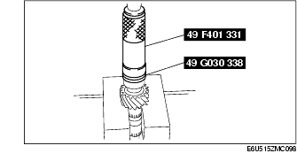
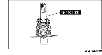
1. Install the front bearing inner race using the SSTs and a press.
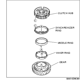
1. Place the 1st gear, 1st inner ring, 1st middle ring, 1st synchronizer ring, 1st/2nd clutch hub.
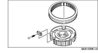
2. Assemble the synchronizer key, spring, steel ball, and clutch hub sleeve as shown in the figure.
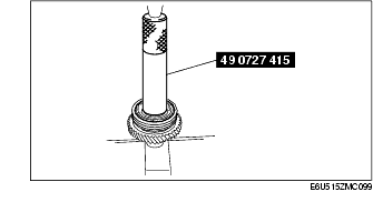
3. Press fit the 1st/2nd clutch hub component using the SST and a press.
1. Place the 2nd synchronizer ring, 2nd middle ring, 2nd inner ring and 2nd gear.
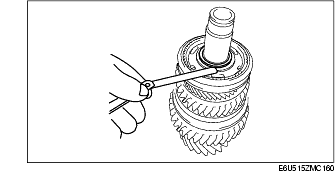
1. Install a new snap ring to the secondary shaft.
2. Measure the clearance between the 2nd inner race and the snap ring.
1. Place the 4th gear, 4th inner ring, 4th middle ring, 4th synchronizer ring and 3rd/4th clutch hub.
2. Assemble the synchronizer key, spring, steel ball, and clutch hub sleeve as shown in the figure.
3. Install the 3rd/4th clutch hub component using the SST and a press.
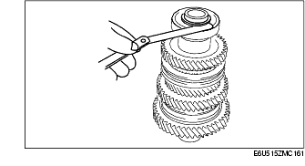
1. Install a new snap ring to the secondary shaft.
2. Measure the clearance between the 3rd/4th clutch hub and the snap ring.
1. Place the 3rd synchronizer ring, 3rd middle ring, 3rd inner ring and 3rd gear.
1. Install the rear bearing using the SSTs and a press.
1. Install a new snap ring to the secondary shaft.
2. Measure the clearance between the rear bearing inner race and the snap ring.