R-3-5 BRAKE CLEARANCE MEASUREMENT/ADJUSTMENT
id051700664900
Preparation Before Servicing
1. Print out the measurement/adjustment value input sheet. (See MEASUREMENT/ADJUSTMENT VALUE INPUT SHEET [EW6A-EL/EW6AX-EL].)(See MEASUREMENT/ADJUSTMENT VALUE INPUT SHEET [FW6A-EL/FW6AX-EL].)
-
Note
-
• When performing the measurement/adjustment, input the measured and calculated values into the measurement/adjustment value input sheet.
• When performing the other measurements/adjustments, if the measurement/adjustment value input sheet has been printed out, use the printed sheet.
R-3-5 Brake Clearance Measurement/Adjustment
1. Measure the retainer thickness of the springs and retainer component.
-
Note
-
• Recommended measuring instrument: Micrometer
• Springs and retainer component size: Inner diameter approx. 148.8 mm {5.858 in}
2. Input the measured retainer thickness of the springs and retainer component into the measurement/adjustment value input sheet.
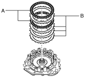
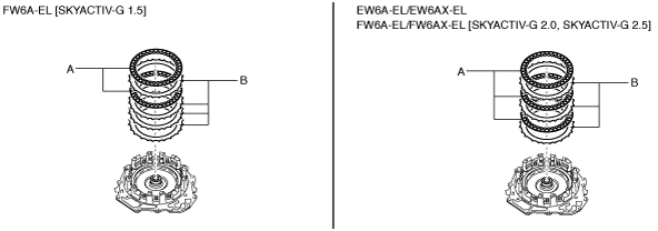
3. Assemble the drive plates and driven plates. (FW6A-EL [SKYACTIV-G 1.5])
-
Note
-
• Drive plate size: Outer diameter approx. 169.4 mm {6.669 in}
• Driven plate size: Inner diameter approx. 141.8 mm {5.583 in}
-
Assembly order
-
Driven plate—driven plate—driven plate—drive plate—driven plate—drive plate
A :Drive plate
B :Driven plate
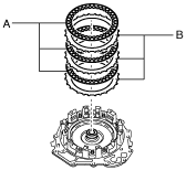
4. Assemble the drive plates and driven plates. (EW6A-EL, EW6AX-EL, FW6A-EL [SKYACTIV-G 2.0, SKYACTIV-G 2.5])
-
Note
-
• Drive plate size: Outer diameter approx. 169.4 mm {6.669 in}
• Driven plate size: Inner diameter approx. 141.8 mm {5.583 in}
-
Assembly order
-
Driven plate—drive plate—driven plate—drive plate—driven plate—drive plate
A :Drive plate
B :Driven plate
5. Assemble the retaining plate.
-
Note
-
• Retaining plate size: Inner diameter approx. 141.8 mm {5.583 in}
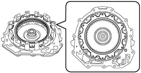
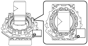
6. Assemble the snap ring (FZ01 19 469) for the R-3-5 brake clearance measurement/adjustment to the position shown in the figure.
-
Caution
-
• Assemble the snap ring so that the end gap of the snap ring is in the area shown in the figure.
• After assembling the snap ring, verify that the snap ring is securely inserted into the bottom of the snap ring groove.
-
Note
-
• Snap ring size: Outer diameter approx. 186.2 mm {7.331 in}
A :End gap of snap ring assembly area
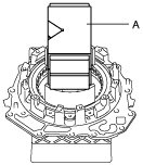
7. Set the end cover for the assembled part on the workbench as shown in the figure.
-
Caution
-
• To reduce error during the R-3-5 brake clearance adjustment value measurement, use the rubber plates to adjust the alignment surface of the end cover with the transaxle case so that it is level.
A :Rubber plate
8. Install the SST.
9. Place a 98—196 N {10.0—19.9 kgf, 23.0—44.0 lbf} weight on the SST.
-
Caution
-
• To reduce error during the R-3-5 brake clearance adjustment value measurement, place the weight near the center of the SST.
-
Note
-
• Use a V-block as a weight.
A :Weight (V-block)
10. Set the measuring instrument to the end cover using the following procedure.
- (1) Install an appropriate steel plate for securing the magnetic stand used in the procedure shown in the figure.
-
-
Caution
-
• If the bolt and nut are tightened with excessive force when installing the steel plate, the alignment surface of the end cover with the transaxle case could be damaged. Tighten the bolt and nut so that the steel plate does not move during the R-3-5 brake clearance adjustment value measurement.
-
Note
-
• When installing the steel plate to the end cover, use an M8 bolt and nut.
|
1
|
Steel plate (for securing magnetic stand)
|
|
2
|
Bolt (M8)
|
|
3
|
Nut (M8)
|
-
Steel plate installation bolt tightening torque
-
15 N·m {1.5 kgf·m, 11 ft·lbf} or less (tighten so that steel plate does not move during R-3-5 brake clearance adjustment value measurement)
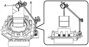
- (2) Set the dial gauge and magnetic stand as shown in the figure.
-
-
Caution
-
• To reduce error during the R-3-5 brake clearance adjustment value measurement, set the dial gauge so that the it is perpendicular to alignment surface of the end cover with the transaxle case.
A :Dial gauge
B :Magnetic stand
- (3) Set the dial gauge end near the center of the weight.
-
-
Caution
-
• To reduce error during the R-3-5 brake clearance adjustment value measurement, set the dial gauge end to within the area shown in the figure.
A :Area in which dial gauge end is set
11. Measure the R-3-5 brake clearance adjustment value using the following procedure:
- (1) Blow compressed air into the oil passage shown in the figure and verify the operation condition of the R-3-5 brake piston (approx. 3 times).
-
-
Warning
-
• Always wear protective eye wear when using the air compressor. Otherwise, ATF or dirt particles blown off by the air compressor could get into the eyes.
-
Caution
-
• To prevent damage to parts, always use an air compressor which is adjusted to the indicated pressure.
-
Compressed air pressure
-
0.39—0.44 MPa {4.0—4.4 kgf/cm2, 57—63 psi}
- (2) Blow compressed air into the oil passage shown in the figure and operate the R-3-5 brake piston to read the value when the dial gauge is stabilized.
-
-
Warning
-
• Always wear protective eye wear when using the air compressor. Otherwise, ATF or dirt particles blown off by the air compressor could get into the eyes.
-
Caution
-
• To prevent damage to parts, always use an air compressor which is adjusted to the indicated pressure.
-
Compressed air pressure
-
0.39—0.44 MPa {4.0—4.4 kgf/cm2, 57—63 psi}
- (3) Input the dial gauge value, which was read while the R-3-5 brake piston was operating, into the measurement/adjustment value input sheet.
-
- (4) Release the compressed air and read the dial gauge value without the R-3-5 brake piston operating.
-
- (5) Input the dial gauge value, which was read without the R-3-5 brake piston operating, into the measurement/adjustment value input sheet.
-
- (6) Perform the following calculation to calculate the R-3-5 brake clearance adjustment value.
-
-
R-3-5 brake clearance adjustment value = B - C
-
B: Dial gauge value with R-3-5 brake piston operated
C: Dial gauge value without R-3-5 brake piston operated
-
Note
-
Example
B: Dial gauge value with R-3-5 brake piston operating is 2.280 mm {0.08976 in}
C: Dial gauge value without R-3-5 brake piston operated is 0.205 mm {0.00807 in}
R-3-5 brake clearance adjustment value = 2.280 mm {0.08976 in} - 0.205 mm {0.00807 in}= 2.075 mm {0.08169 in}
- (7) Input the calculated R-3-5 brake clearance adjustment value into the measurement/adjustment value input sheet.
-
- (8) Verify that the R-3-5 brake clearance satisfies the specification.
-
-
Specification
-
1.180—1.380 mm {0.04646—0.05433 in}
-
• If not within the specification, adjust the R-3-5 brake clearance.
12. Remove the dial gauge and magnetic stand.
A :Dial gauge
B :Magnetic stand
13. Remove the steel plate for securing the magnetic stand using the procedure shown in the figure.
|
1
|
Nut (M8)
|
|
2
|
Bolt (M8)
|
|
3
|
Steel plate (for securing magnetic stand)
|
14. Remove the weight on the SST.
A :Weight (V-block)
15. Remove the SST.
16. Take the end cover off the rubber plates.
17. Remove the snap ring (FZ01 19 469) for the R-3-5 brake clearance measurement/adjustment.
18. Measure the thickness of the removed snap ring (FZ01 19 469) for the R-3-5 brake clearance measurement/adjustment.
-
Note
-
• Recommended measuring instrument: Micrometer
19. Input the measured snap ring (FZ01 19 469) thickness for the R-3-5 brake clearance measurement/adjustment into the measurement/adjustment value input sheet.
20. Select the appropriate snap ring from the following table:
|
Range*
|
Selected snap ring thickness
|
|
Exceeds 3.930 mm {0.1547 in}, 4.030 mm {0.1587 in} or less
|
2.7 mm {0.106 in}
|
|
Exceeds 3.830 mm {0.1508 in}, 3.930 mm {0.1547 in} or less
|
2.6 mm {0.102 in}
|
|
Exceeds 3.730 mm {0.1469 in}, 3.830 mm {0.1508 in} or less
|
2.5 mm {0.098 in}
|
|
Exceeds 3.630 mm {0.1429 in}, 3.730 mm {0.1469 in} or less
|
2.4 mm {0.094 in}
|
|
Exceeds 3.530 mm {0.1390 in}, 3.630 mm {0.1429 in} or less
|
2.3 mm {0.091 in}
|
|
Exceeds 3.430 mm {0.1350 in}, 3.530 mm {0.1390 in} or less
|
2.2 mm {0.087 in}
|
|
Exceeds 3.330 mm {0.1311 in}, 3.430 mm {0.1350 in} or less
|
2.1 mm {0.083 in}
|
|
Exceeds 3.230 mm {0.1272 in}, 3.330 mm {0.1311 in} or less
|
2.0 mm {0.079 in}
|
|
Exceeds 3.130 mm {0.1232 in}, 3.230 mm {0.1272 in} or less
|
1.9 mm {0.075 in}
|
|
Exceeds 3.030 mm {0.1193 in}, 3.130 mm {0.1232 in} or less
|
1.8 mm {0.071 in}
|
* :The range is the thickness of the removed snap ring (FZ01 19 469) used for the R-3-5 brake clearance measurement/adjustment added to the R-3-5 brake clearance adjustment value, from which the retainer thickness of the springs and retainer component is subtracted.
-
Range = D + E - A
-
A: Retainer thickness of springs and retainer component
D: R-3-5 brake clearance adjustment value
E: Thickness of snap ring (FZ01 19 469) for R-3-5 brake clearance measurement/adjustment
-
Note
-
Example
A: Retainer thickness of springs and retainer component is 1.225 mm {0.04823 in}
D: R-3-5 brake clearance adjustment value is 2.075 mm {0.08169 in}
E: Thickness of snap ring (FZ01 19 469) for R-3-5 brake clearance measurement/adjustment is 2.625 mm {0.10335 in}
Range = 2.075 mm {0.08169 in}+ 2.625 mm {0.10335 in} - 1.225 mm {0.04823 in}= 3.475 mm {0.13681 in}, the selected snap ring has a thickness of 2.3 mm {0.091 in}.
21. Remove the retaining plate.
22. Remove the drive plates and driven plates.
A :Drive plate
B :Driven plate