SECONDARY GEAR AND OUTPUT GEAR PRELOAD MEASUREMENT/ADJUSTMENT [FW6A-EL/FW6AX-EL]
id0517006650z3
Preparation Before Servicing
1. Print out the measurement/adjustment value input sheet. (See MEASUREMENT/ADJUSTMENT VALUE INPUT SHEET [FW6A-EL/FW6AX-EL].)
-
Note
-
• When performing the measurement/adjustment, input the measured and calculated values into the measurement/adjustment value input sheet.
• When performing the other measurements/adjustments, if the measurement/adjustment value input sheet has been printed out, use the printed sheet.
Secondary Gear and Output Gear Preload Measurement
1. Rotate and adjust the rotation handle of the engine stand so that the converter housing side is facing upward.
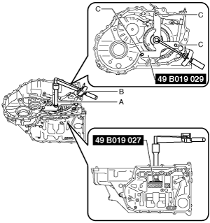
2. Rotate the parking shift lever component to the N position as shown in the figure.
A :Parking shift lever component
B :Manual plate component
C :Detent bracket component
3. Remove any remaining old sealant on the contact surfaces of the transaxle case and converter housing.
4. Measure the angular contact ball bearing preload using the following procedure:
- (1) Set the SSTs, extension bar, and torque wrench as shown in the figure.
-
A :Extension bar
B :Torque wrench
C :Bolt supplied with SST (49 B019 029) or M8×1.25, length to 18 mm {0.71 in}
A :Extension bar
B :Torque wrench
C :Bolt supplied with SST (49 B019 029) or M8×1.25, length to 18 mm {0.71 in}
- (2) Rotate the locknut (primary gear) in the direction of the arrow shown in the figure using a torque wrench and measure the angular contact ball bearing preload.
-
-
Caution
-
• After rotating the locknut (primary gear) approx. 10 times in the direction of the arrow shown in the figure, measure the angular contact ball bearing preload to engage the angular contact ball bearing.
• When the locknut (primary gear) is rotated at approx. 20 rpm (speed of one rotation for 3 s), measure the rotational torque as the angular contact ball bearing preload.
- (3) Input the measured angular contact ball bearing preload into the measurement/adjustment value sheet.
-
- (4) Remove the torque wrench.
-
-
Note
-
• Because the SSTs and extension bar are used for secondary gear and output gear preload measurement/adjustment, do not remove them.
A :Torque wrench
5. Assemble the secondary gear and output gear using the following procedure:
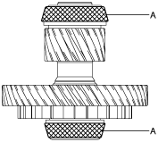
- (1) Apply ATF (ATF FZ) to the taper roller bearing roller of the secondary gear and output gear.
-
-
Caution
-
• Accurately perform the procedure to reduce the error on the secondary gear and output gear preload measurement.
A :ATF application area
- (2) Assemble the secondary gear and output gear.
-
6. Assemble the bearing race and a new shim with the same thickness as the removed shim to the converter housing using the following procedure:
-
Caution
-
• Always use a new shim. If a deformed shim is reused, it may cause a transaxle malfunction.
- (1) Apply ATF (ATF FZ) to the engagement area of the bearing race and converter housing.
-
- (2) Assemble the bearing race and a new shim with the same thickness as the removed shim using the following procedure and the SST:
-
|
1
|
Shim (outer diameter approx. 74 mm {2.9 in})
(new shim with same thickness of removed shim)
|
|
2
|
Bearing race (outer diameter approx. 75 mm {3.0 in})
|
7. Assemble the converter housing using the following procedure:
|
1
|
Converter housing
|
|
2
|
24 bolts (M8×1.25 bolt, length to approx. 28 mm {1.1 in})
|
- (1) Assemble the converter housing.
-
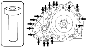
- (2) Assemble and temporarily tighten the bolts to the positions shown in the figure.
-
-
Note
-
• Bolt size: M8×1.25 bolt, length to approx. 28 mm {1.1 in}
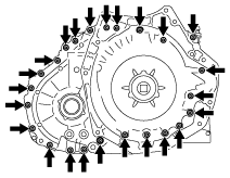
- (3) Assemble and temporarily tighten the bolts to the positions shown in the figure.
-
-
Caution
-
• When performing the automatic transaxle assembly after the secondary gear and output gear preload measurement/adjustment, use new bolts, otherwise ATF leakage could occur.
-
Note
-
• The bolts for the assembly are applied with sealant. However, the bolts are reused for removal after the secondary gear and output gear preload measurement/adjustment.
• Bolt size: M8×1.25 bolt, length to approx. 28 mm {1.1 in}
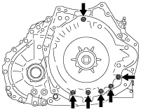
- (4) Tighten the bolts shown in the figure.
-
-
Tightening torque
-
19—25 N·m {2.0—2.5 kgf·m, 15—18 ft·lbf}
8. Measure the total preload using the following procedure:
-
Note
-
• The total preload is the combined preload of the angular contact ball bearing preload and secondary gear and output gear preload.
- (1) Set the torque wrench to the extension bar as shown in the figure.
-
A :Extension bar
B :Torque wrench
A :Extension bar
B :Torque wrench
- (2) Rotate the locknut (primary gear) in the direction of the arrow shown in the figure using a torque wrench and measure the total preload.
-
-
Caution
-
• Measure the total preload after rotating the locknut (primary gear) approx. 10 times in the direction of the arrow shown in the figure to engage the taper roller bearing.
• When the locknut (primary gear) is rotated at approx. 20 rpm (speed of one rotation for 3 s), measure the rotational torque as the total preload.
- (3) Input the measured total preload into the measurement/adjustment value sheet.
-
- (4) Remove the torque wrench from the extension bar.
-
A :Extension bar
B :Torque wrench
9. Remove the converter housing using the following procedure:
|
1
|
24 bolts
|
|
2
|
Converter housing
|
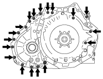
- (1) Remove the bolts shown in the figure.
-
-
Caution
-
• Sealant has been applied to the removed bolts. If the bolts are reused it could cause ATF leakage, therefore when performing the automatic transaxle assembly, use new bolts.
- (2) Remove the bolts shown in the figure.
-
- (3) Remove the converter housing.
-
10. Perform the following calculation to calculate the secondary gear and output gear preload.
-
Secondary gear and output gear preload = B - A
-
A: Angular contact ball bearing preload
B: Total preload
-
Note
-
Example
A: Angular contact ball bearing preload is 1.2 N·m {12.2 kgf·cm, 10.6 in·lbf}
B: Total preload is 2.6 N·m {26.5 kgf·cm, 23.0 in·lbf}
Secondary gear and output gear preload = 2.6 N·m {26.5 kgf·cm, 23.0 in·lbf} - 1.2 N·m {12.2 kgf·cm, 10.6 in·lbf}= 1.4 N·m {14.3 kgf·cm, 12.4 in·lbf}
11. Input the calculated secondary gear and output gear preload into the measurement/adjustment value sheet.
12. Verify that the secondary gear and output gear preload satisfies the specification.
-
Specification
-
2WD: 2.8—3.7 N·m {29—37 kgf·cm, 25—32 in·lbf}
4WD: 1.6—3.4 N·m {17—34 kgf·cm, 15—30 in·lbf}
-
13. Remove the secondary gear and output gear.
14. Remove the SST and extension bar.
A :Extension bar
B :Bolt supplied with SST (49 B019 029) or M8×1.25, length to 18 mm {0.71 in}
15. Rotate the parking shift lever component to the P position as shown in the figure.
A :Parking shift lever component
B :Manual plate component
C :Detent bracket component
Secondary Gear and Output Gear Preload Adjustment
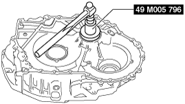
1. Remove the bearing race and shim from the converter housing using the SST and procedure shown in the figure.
-
Caution
-
• Because the shim will deform when removing the bearing race, use a new shim when performing the shim assembly.
2. Measure the thickness of the removed shim.
-
Note
-
• Recommended measuring instrument: Micrometer
3. Input the measured shim thickness into the measurement/adjustment value sheet.
4. Perform the following calculation to calculate the preload gap.
-
Note
-
• The preload gap is the difference between the secondary gear and output gear preload and the median value of the secondary gear and output gear preload specification.
-
Preload gap = G - C
-
C: Secondary gear and output gear preload
G: Median value of secondary gear and output gear preload specification (2WD: 3.25 N·m {33.1 kgf·cm, 28.7 in·lbf}) (4WD: 2.5 N·m {25.5 kgf·cm, 22.1 in·lbf})
-
Note
-
Example
C: Secondary gear and output gear preload is 1.4 N·m {14.3 kgf·cm, 12.4 in·lbf}
Preload gap = 2.5 N·m {25.5 kgf·cm, 22.1 in·lbf} - 1.4 N·m {14.3 kgf·cm, 12.4 in·lbf}= 1.1 N·m {11.2 kgf·cm, 9.7 in·lbf}
5. Input the calculated preload gap into the measurement/adjustment value sheet.
6. Perform the following calculation to calculate the gap in the shim thickness.
-
Note
-
• The gap in the shim thickness is the difference between the removed shim thickness and the optimum shim thickness.
• If the shim thickness is thickened 0.1 mm {0.00394 in}, the secondary gear and output gear preload increases approx. 2.0 N·m {20.4 kgf·cm, 17.7 in·lbf}.
-
Shim thickness gap = H × 0.1 mm {0.00394 in} / 2.0 N·m {20.4 kgf·cm, 17.7 in·lbf}
-
H: Preload gap
-
Note
-
Example
H: Preload gap is 1.1 N·m {11.2 kgf·cm, 9.7 in·lbf}
Shim thickness gap = 1.1 N·m {11.2 kgf·cm, 9.7 in·lbf}× 0.1 mm {0.00394 in} / 2.0 N·m {20.4 kgf·cm, 17.7 in·lbf}= 0.055 mm {0.00217 in}
7. Input the calculated shim thickness gap into the measurement/adjustment value sheet.
8. Perform the following calculation to calculate the optimum shim thickness.
-
Optimum shim thickness = F + I
-
F: Thickness of removed shim
I: Shim thickness gap
-
Note
-
Example
F: Thickness of removed shim is 0.855 mm {0.03366 in}
I: Shim thickness gap is 0.055 mm {0.00217 in}
Thickness of optimum shim = 0.855 mm {0.03366 in}+ 0.055 mm {0.00217 in}= 0.91 mm {0.03583 in}
9. Input the calculated optimum shim thickness into the measurement/adjustment value sheet.
10. Select the nearest new shim for the calculated optimum shim thickness from the following table:
|
Selected shim thickness
|
|
1.45 mm {0.0571 in}
|
|
1.40 mm {0.0551 in}
|
|
1.35 mm {0.0531 in}
|
|
1.30 mm {0.0512 in}
|
|
1.25 mm {0.0492 in}
|
|
1.20 mm {0.0472 in}
|
|
1.15 mm {0.0453 in}
|
|
1.10 mm {0.0433 in}
|
|
1.05 mm {0.0413 in}
|
|
1.00 mm {0.0394 in}
|
|
0.95 mm {0.0374 in}
|
|
0.90 mm {0.0354 in}
|
|
0.85 mm {0.0335 in}
|
|
0.80 mm {0.0315 in}
|
|
0.75 mm {0.0295 in}
|
|
0.70 mm {0.0276 in}
|
|
0.65 mm {0.0256 in}
|
|
0.60 mm {0.0236 in}
|
|
0.55 mm {0.0217 in}
|
|
0.50 mm {0.0197 in}
|
11. Assemble the bearing race and selected new shim to the converter housing using the following procedure:
-
Caution
-
• Always use a new shim. If a deformed shim is reused, it may cause a transaxle malfunction.
- (1) Apply ATF (ATF FZ) to the engagement area of the bearing race and converter housing.
-
- (2) Assemble the bearing race and selected new shim using the following procedure and SST:
-
|
1
|
Shim (outer diameter approx. 74 mm {2.9 in})
(selected new shim)
|
|
2
|
Bearing race (outer diameter approx. 75 mm {3.0 in})
|
12. Perform the secondary gear and output gear preload measurement from Step 7. (See Secondary Gear and Output Gear Preload Measurement.)