|
1
|
VERIFY RELATED SERVICE INFORMATION AVAILABILITY
• Verify related Service Information availability.
• Is any related Service Information available?
|
Yes
|
Perform repair or diagnosis according to the available Service Information.
• If the vehicle is not repaired, go to the next step.
|
|
No
|
Go to the next step.
|
|
2
|
VERIFY RELATED PENDING CODE AND/OR DTC
• Switch the ignition to off, then to ON (engine off).
• Perform the Pending Trouble Code Access Procedure and DTC Reading Procedure.
• Is the PENDING CODE/or DTC P0B25:00 or P0B29:00 also present?
|
Yes
|
Go to the applicable PENDING CODE or DTC inspection.
|
|
No
|
Go to the next step.
|
|
3
|
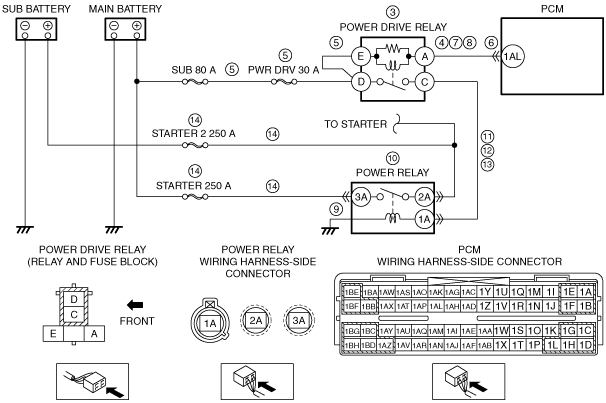
INSPECT POWER DRIVE RELAY
• Switch the ignition to off.
• Remove the power drive relay.
• Inspect the power drive relay.
• Is there any malfunction?
|
Yes
|
Replace the power drive relay, then go to Step 15.
|
|
No
|
Go to the next step.
|
|
4
|
INSPECT POWER DRIVE RELAY SIGNAL CIRCUIT FOR SHORT TO GROUND
• Power drive relay is removed.
• Inspect for continuity between power drive relay terminal A (wiring harness-side) and body ground.
• Is there continuity?
|
Yes
|
If the short to ground circuit could be detected:
• Repair or replace the wiring harness for a possible short to ground.
If the short to ground circuit could not be detected:
• Replace the PCM (short to ground in PCM internal circuit).
Go to Step 15.
|
|
No
|
Go to the next step.
|
|
5
|
INSPECT POWER DRIVE RELAY POWER SUPPLY CIRCUIT FOR SHORT TO GROUND OR OPEN CIRCUIT
• Power drive relay is removed.
• Measure the voltage at the following terminals (wiring harness-side):
-
― Power drive relay terminal E
― Power drive relay terminal D
• Is the voltage B+?
|
Yes
|
Go to the next step.
|
|
No
|
Inspect the PWR DRV 30 A fuse.
• If the fuse is melt:
-
― Repair or replace the wiring harness for a possible short to ground.
― Replace the fuse.
• If the fuse is deterioration:
-
― Replace the fuse.
• If the fuse is normal:
-
― Repair or replace the wiring harness for a possible open circuit.
Go to Step 15.
|
|
6
|
INSPECT PCM CONNECTOR CONDITION
• Disconnect the PCM connector.
• Inspect for poor connection (such as damaged/pulled-out pins, corrosion).
• Is there any malfunction?
|
Yes
|
Repair or replace the terminal and/or connector, then go to Step 15.
|
|
No
|
Go to the next step.
|
|
7
|
INSPECT POWER DRIVE RELAY SIGNAL CIRCUIT FOR OPEN CIRCUIT
• Power drive relay is removed.
• PCM connector is disconnected.
• Inspect for continuity between power drive relay terminal A (wiring harness-side) and PCM terminal 1AL (wiring harness-side).
• Is there continuity?
|
Yes
|
Go to the next step.
|
|
No
|
Repair or replace the wiring harness for a possible open circuit, then go to Step 15.
|
|
8
|
INSPECT POWER DRIVE RELAY SIGNAL CIRCUIT FOR SHORT TO POWER SUPPLY
• Power drive relay is removed.
• PCM connector is disconnected.
• Switch the ignition to ON (engine off).
• Measure the voltage at the power drive relay terminal A (wiring harness-side).
• Is there any voltage?
|
Yes
|
Repair or replace the wiring harness for a possible short to power supply, then go to Step 15.
|
|
No
|
Go to the next step.
|
|
9
|
INSPECT POWER RELAY GROUND FOR OPEN CIRCUIT
• Switch the ignition to off.
• Inspect the installation of power relay.
• Is the power relay installed securely?
|
Yes
|
Go to the next step.
|
|
No
|
Retighten the power relay, then go to Step 15.
|
|
10
|
INSPECT POWER RELAY
• Remove the power relay.
• Inspect the power relay.
• Is there any malfunction?
|
Yes
|
Replace the power relay, then go to Step 15.
|
|
No
|
Go to the next step.
|
|
11
|
INSPECT POWER RELAY POWER SUPPLY CIRCUIT FOR SHORT TO GROUND
• Power drive relay and power relay are removed.
• PCM connector is disconnected.
• Inspect for continuity between power relay terminal 1A (wiring harness-side) and body ground.
• Is there continuity?
|
Yes
|
Repair or replace the wiring harness for a possible short to ground, then go to Step 15.
|
|
No
|
Go to the next step.
|
|
12
|
INSPECT POWER RELAY POWER SUPPLY CIRCUIT FOR SHORT TO POWER SUPPLY
• Power drive relay and power relay are removed.
• PCM connector is disconnected.
• Switch the ignition to ON (engine off).
• Measure the voltage at the power relay terminal 1A (wiring harness-side).
• Is there any voltage?
|
Yes
|
Repair or replace the wiring harness for a possible short to power supply, then go to Step 15.
|
|
No
|
Go to the next step.
|
|
13
|
INSPECT POWER RELAY POWER SUPPLY CIRCUIT FOR OPEN CIRCUIT
• Power drive relay and power relay are removed.
• PCM connector is disconnected.
• Switch the ignition to off.
• Inspect for continuity between power drive relay terminal C (wiring harness-side) and power relay terminal 1A (wiring harness-side).
• Is there continuity?
|
Yes
|
Go to the next step.
|
|
No
|
Repair or replace the wiring harness for a possible open circuit, then go to Step 15.
|
|
14
|
INSPECT POWER RELAY CIRCUIT FOR SHORT TO GROUND OR OPEN CIRCUIT
• Power drive relay and power relay are removed.
• PCM connector is disconnected.
• Measure the voltage at the following terminals (wiring harness-side):
-
― Power relay terminal 2A
― Power relay terminal 3A
• Is the voltage B+?
|
Yes
|
Go to the next step.
|
|
No
|
Inspect the STARTER 250 A fuse and STARTER 2 250 A fuse.
• If the fuse is melt:
-
― Repair or replace the wiring harness for a possible short to ground.
― Replace the malfunctioning fuse.
• If the fuse is deterioration:
-
― Replace the malfunctioning fuse.
• If the fuse is normal:
-
― Repair or replace the wiring harness for a possible open circuit.
Go to the next step.
|
|
15
|
VERIFY DTC TROUBLESHOOTING COMPLETED
• Make sure to reconnect all disconnected connectors.
• Clear the DTC from the PCM memory using the M-MDS.
• Perform the KOEO or KOER self test.
• Is the same DTC present?
|
Yes
|
Repeat the inspection from Step 1.
• If the malfunction recurs, replace the PCM.
Go to the next step.
|
|
No
|
Go to the next step.
|
|
16
|
VERIFY AFTER REPAIR PROCEDURE
• Perform the “AFTER REPAIR PROCEDURE”.
• Are any DTCs present?
|
Yes
|
Go to the applicable DTC inspection.
|
|
No
|
DTC troubleshooting completed.
|