 |
am3zzw00011908
PCM REMOVAL/INSTALLATION [MZR 2.0 DISI i-stop]
id0140j1802400
Operation After Replacing PCM
|
STEP |
ACTION |
NOTE |
|---|---|---|
|
1
|
Replace the PCM.
|
—
|
|
2
|
Perform the PCM configuration using the M-MDS.
|
—
|
|
3
|
Close the bonnet.
|
• Because the sub battery recharge is not available while the bonnet is open, the procedure is not completed.
|
|
4
|
Warm up the engine. (No electrical load)
|
—
|
|
5
|
Switch the ignition off.
|
—
|
|
6
|
Long-press the i-stop OFF switch for 3 s within 5 s after switching the ignition ON.
|
—
|
|
7
|
Start the engine.
|
—
|
|
8
|
Press the i-stop OFF switch.
Verify that the i-stop indicator light (green) flashes.
• If it does not flash, go back to Step 6.
|
—
|
|
9
|
Maintain the idle status (no electrical load) until the i-stop indicator light (green) turns off.
|
• For operating i-stop, learning is required for the following two items:
Initial learning/recharging for battery charge condition
ISC learning
• If the above two operations are successfully completed, the i-stop indicator light (green) turns off.
|
|
10
|
Verify that the engine stops via the i-stop control and then restarts.
• If it cannot be verified, inspect the i-stop system-related units for DTCs.
|
|
|
11
|
Switch the ignition off, and start the engine.
|
• The display function for the i-stop indicator light (green) is reset.
|
Without Set Bolt
1. Remove the battery cover. (See BATTERY REMOVAL/INSTALLATION [MZR 2.0 DISI i-stop].)
2. Disconnect the negative battery cable. (See BATTERY REMOVAL/INSTALLATION [MZR 2.0 DISI i-stop].)
3. Remove the front side trim (passenger-side). (See FRONT SIDE TRIM REMOVAL/INSTALLATION.)
4. Remove the front scuff plate (passenger-side). (See FRONT SCUFF PLATE REMOVAL/INSTALLATION.)
5. Remove the side wall (passenger-side). (See SIDE WALL REMOVAL/INSTALLATION.)
6. Partially peek back the floor covering.
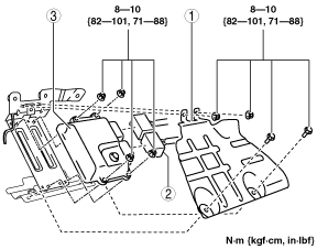
7. Remove in the order indicated in the table.
am3zzw00011908
|
|
1
|
PCM cover
|
|
2
|
PCM connector (See PCM Connector Connection Note.)
|
|
3
|
PCM (See Operation After Replacing PCM.)
|
8. Install in the reverse order of removal.
9. When replacing the PCM, perform the following:
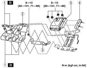
With Set Bolt
1. Remove the battery cover. (See BATTERY REMOVAL/INSTALLATION [MZR 2.0 DISI i-stop].)
2. Disconnect the negative battery cable. (See BATTERY REMOVAL/INSTALLATION [MZR 2.0 DISI i-stop].)
3. Remove the front side trim (passenger-side). (See FRONT SIDE TRIM REMOVAL/INSTALLATION.)
4. Remove the front scuff plate (passenger-side). (See FRONT SCUFF PLATE REMOVAL/INSTALLATION.)
5. Remove the side wall (passenger-side). (See SIDE WALL REMOVAL/INSTALLATION.)
6. Partially peek back the floor covering.
7. Remove in the order indicated in the table.
am3zzw00011909
|
|
1
|
Set bolt
(See Set Bolt Removal Note.)
(See Set Bolt Installation Note.)
|
|
2
|
PCM cover
|
|
3
|
PCM bracket No.1
|
|
4
|
PCM connector (See PCM Connector Connection Note.)
|
|
5
|
PCM (See Operation After Replacing PCM.)
|
8. Install in the reverse order of removal.
9. When replacing the PCM, perform the following:
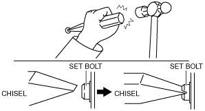
Set Bolt Removal Note
1. Using a chisel and a hammer, cut a groove on the head of the set bolt so that a screwdriver can be inserted.
2. Loose the set bolt using an impact screwdriver or pliers.
am3zzw00011910
|
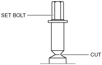
Set Bolt Installation Note
1. Install a new set bolt and tighten it until the neck of the bolt is cut.
am3zzw00011911
|
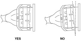
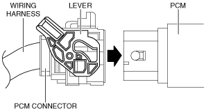
PCM Connector Connection Note
am3zzw00011912
|
1. Verify that the PCM connector lever is tilted towards the wiring harness side as shown in the figure.
am3zzw00011913
|
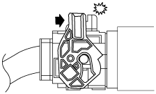
2. Insert the PCM connector straight until it contacts the PCM and verify that the lever reverts upward naturally.
3. Push the lever until a click is heard.
am3zzw00011914
|