|
1
|
IDENTIFY TRIGGER DTC FOR FREEZE FRAME DATA (MODE 2)
• Perform the Freeze Frame PID Data Access Procedure.
• Is the DTC P0137:00 on FREEZE FRAME DATA (Mode 2)?
|
Yes
|
Go to the next step.
|
|
No
|
Go to the troubleshooting procedures for DTC on FREEZE FRAME DATA (Mode 2).
|
|
2
|
VERIFY FREEZE FRAME DATA (MODE 2)/SNAPSHOT DATA AND DIAGNOSTIC MONITORING TEST RESULTS HAVE BEEN RECORDED
• Have the FREEZE FRAME DATA (Mode 2)/snapshot data and DIAGNOSTIC MONITORING TEST RESULTS (A/F sensor, HO2S related) been recorded?
|
Yes
|
Go to the next step.
|
|
No
|
Record the FREEZE FRAME DATA (Mode 2)/snapshot data and DIAGNOSTIC MONITORING TEST RESULTS on repair order, then go to the next step.
|
|
3
|
VERIFY RELATED SERVICE INFORMATION AVAILABILITY
• Verify related Service Information availability.
• Is any related Service Information available?
|
Yes
|
Perform repair or diagnosis according to the available Service Information.
• If the vehicle is not repaired, go to the next step.
|
|
No
|
Go to the next step.
|
|
4
|
VERIFY RELATED PENDING CODE AND STORED DTC
• Switch the ignition to off, then to ON (engine off).
• Verify the related PENDING CODE and stored DTCs using the M-MDS.
• Are any other DTCs present?
|
Yes
|
Go to the applicable DTC inspection.
|
|
No
|
Go to the next step.
|
|
5
|
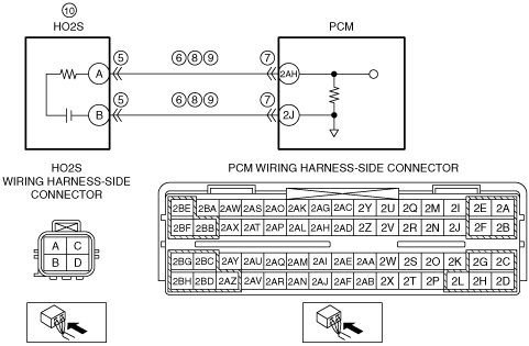
INSPECT HO2S CONNECTOR AND TERMINALS
• Switch the ignition to off.
• Disconnect the HO2S connector.
• Inspect for poor connection (such as damaged/pulled-out pins, and corrosion).
• Is there any malfunction?
|
Yes
|
Repair or replace the connector or terminals, then go to Step 11.
|
|
No
|
Go to the next step.
|
|
6
|
INSPECT HO2S CIRCUIT FOR SHORT TO GROUND
• HO2S connector is disconnected.
• Inspect for continuity between the following terminals (wiring harness-side) and body ground:
-
― HO2S terminal A
― HO2S terminal B
• Is there continuity?
|
Yes
|
If the short to ground circuit could be detected:
• Repair or replace the wiring harness for a possible short to ground.
If the short to ground circuit could not be detected:
• Replace the PCM (short to ground in PCM internal circuit).
Go to Step 11.
|
|
No
|
Go to the next step.
|
|
7
|
INSPECT PCM CONNECTOR AND TERMINALS
• Disconnect the PCM connector.
• Inspect for poor connection (such as damaged/pulled-out pins, and corrosion).
• Is there any malfunction?
|
Yes
|
Repair or replace the connector or terminals, then go to Step 11.
|
|
No
|
Go to the next step.
|
|
8
|
INSPECT HO2S CIRCUITS FOR SHORT TO EACH OTHER
• HO2S and PCM connectors are disconnected.
• Inspect for continuity between HO2S terminals A and B (wiring harness-side).
• Is there continuity?
|
Yes
|
Repair or replace the wiring harness for a possible short to each other, then go to Step 11.
|
|
No
|
Go to the next step.
|
|
9
|
INSPECT HO2S CIRCUIT FOR OPEN CIRCUIT
• HO2S and PCM connectors are disconnected.
• Inspect for continuity between the following terminals (wiring harness-side):
-
― HO2S terminal A—PCM terminal 2AH
― HO2S terminal B—PCM terminal 2J
• Is there continuity?
|
Yes
|
Go to the next step.
|
|
No
|
Repair or replace the wiring harness for a possible open circuit, then go to Step 11.
|
|
10
|
INSPECT HO2S
• Reconnect the HO2S and PCM connectors.
• Is there any malfunction?
|
Yes
|
Replace the HO2S, then go to the next step.
|
|
No
|
Go to the next step.
|
|
11
|
VERIFY DTC TROUBLESHOOTING COMPLETED
• Make sure to reconnect all disconnected connectors.
• Clear the DTC from the PCM memory using the M-MDS.
• Perform the Drive Mode 03 (A/F sensor heater, HO2S heater, A/F sensor, HO2S and TWC Repair Verification Drive Mode).
• Is the PENDING CODE for this DTC present?
|
Yes
|
Repeat the inspection from Step 1.
• If the malfunction recurs, replace the PCM.
Go to the next step.
|
|
No
|
Go to the next step.
|
|
12
|
VERIFY AFTER REPAIR PROCEDURE
• Perform the “AFTER REPAIR PROCEDURE”.
• Are any DTCs present?
|
Yes
|
Go to the applicable DTC inspection.
|
|
No
|
DTC troubleshooting completed.
|