|
1
|
IDENTIFY TRIGGER DTC FOR FREEZE FRAME DATA (MODE2)
• Is DTC P0134:00 on FREEZE FRAME DATA (mode2)?
|
Yes
|
Go to the next step.
|
|
No
|
Go to troubleshooting procedures for DTC on FREEZE FRAME DATA (mode2).
|
|
2
|
VERIFY FREEZE FRAME DATA (MODE2) OR SNAPSHOT DATA HAVE BEEN RECORDED
• Have FREEZE FRAME DATA (mode2) or snapshot data been recorded?
|
Yes
|
Go to the next step.
|
|
No
|
Record the FREEZE FRAME DATA (mode2) and snapshot data on the repair order, then go to the next step.
|
|
3
|
VERIFY RELATED SERVICE INFORMATION AVAILABILITY
• Verify related Service Information availability.
• Is any related Service Information available?
|
Yes
|
Perform repair or diagnosis according to the available Service Information.
• If the vehicle is not repaired, go to the next step.
|
|
No
|
Go to the next step.
|
|
4
|
VERIFY RELATED PENDING AND STORED DTC
-
Note
-
• If fuel monitor, DTC P0132:00 is retrieved, ignore it until P0134:00 is fixed.
• Switch the ignition to off, then to the ON position (Engine off).
• Verify pending and stored DTCs using the M-MDS.
• Are other DTCs present?
|
Yes
|
Go to the appropriate DTC troubleshooting procedures.
|
|
No
|
Go to the next step.
|
|
5
|
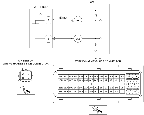
INSPECT A/F SENSOR SIGNAL CIRCUIT FOR SHORT TO GROUND
• Switch the ignition off.
• Disconnect the A/F sensor connector.
• Inspect for continuity between the A/F sensor terminal A (wiring harness-side) to body ground.
• Is there continuity?
|
Yes
|
If the short to ground circuit could be detected:
• Repair or replace the wiring harness for a possible short to ground.
If the short to ground circuit could not be detected:
• Replace the PCM (short to ground in the PCM internal circuit).
Go to Step 8.
|
|
No
|
Go to the next step.
|
|
6
|
INSPECT A/F SENSOR SIGNAL CIRCUIT FOR OPEN CIRCUIT
• A/F sensor connector is disconnected.
• Disconnect the PCM connector.
• Inspect for continuity between the A/F sensor terminal A (wiring harness-side) to the PCM terminal 2AF (wiring harness-side).
• Is there continuity?
|
Yes
|
Go to the next step
|
|
No
|
Repair or replace the wiring harness for a possible open circuit, then go to Step 8.
|
|
7
|
INSPECT A/F SENSOR
• Is there any malfunction?
|
Yes
|
Replace the A/F sensor, then go to the next step.
|
|
No
|
Go to the next step
|
|
8
|
VERIFY TROUBLESHOOTING OF DTC P0134:00 COMPLETED
• Make sure to reconnect all disconnected connectors.
• Clear the DTC from the PCM memory using the M-MDS.
• Perform the Repair Verification Drive Mode.
• Is the same DTC present?
|
Yes
|
Repeat the inspection from Step 1.
• If the malfunction recurs, replace the PCM.
Go to the next step.
|
|
No
|
Go to the next step.
|
|
9
|
VERIFY AFTER REPAIR PROCEDURE
• Perform the “AFTER REPAIR PROCEDURE”.
• Are any DTCs present?
|
Yes
|
Go to the applicable DTC inspection.
|
|
No
|
DTC troubleshooting completed.
|