 |
am3zzw00007775
FUEL INJECTOR REMOVAL/INSTALLATION [MZR 2.0 DISI i-stop]
id0114b9800600
1. Complete the “BEFORE SERVICE PRECAUTION”. (See BEFORE SERVICE PRECAUTION [MZR 2.0 DISI i-stop].)
2. Remove the battery cover. (See BATTERY REMOVAL/INSTALLATION [MZR 2.0 DISI i-stop].)
3. Disconnect the negative battery cable. (See BATTERY REMOVAL/INSTALLATION [MZR 2.0 DISI i-stop].)
4. Remove the intake manifold. (See INTAKE-AIR SYSTEM REMOVAL/INSTALLATION [MZR 2.0 DISI i-stop].)
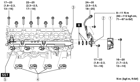
5. Remove in the order indicated in the table.
6. Install in the reverse order of removal.
7. Complete the “AFTER SERVICE PRECAUTION”. (See AFTER SERVICE PRECAUTION [MZR 2.0 DISI i-stop].)
am3zzw00007775
|
|
1
|
Intake manifold stay
|
|
2
|
High pressure line pipe
|
|
3
|
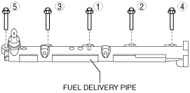
Fuel delivery pipe
|
|
4
|
Fuel injector bracket
|
|
5
|
Fuel injector
(See Fuel Injector Removal Note.)
|
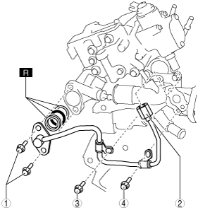
High Pressure Line Pipe Removal Note
1. Drain the engine coolant. (See ENGINE COOLANT REPLACEMENT [MZR 2.0 DISI i-stop].)
2. Disconnect the high pressure line pipe by following procedure.
am3zzw00007776
|
3. Remove the high pressure line pipe.
Fuel Injector Removal Note
1. Install the SST to the fuel injector confirming that the SST faces the correct direction as shown in the figure.
am3zzw00012051
|
am3zzw00012052
|
2. Keep ratcheting the SST so that the fuel injector becomes free enough to ratchet up without using the SST.
3. Pull out the fuel injector by ratcheting it upright.
4. Verify that there are no gasket in the cylinder heads after removing the injectors.
5. Clean the fuel injector and around the insertion hole using a vacuum cleaner.
Fuel Delivery Pipe Installation Note
am3zzw00007779
|
High Pressure Line Pipe Installation Note
1. Temporarily tighten shown in the figure.
am3zzw00016444
|
|
1
|
High pressure line pipe installation bolts
|
|
2
|
High pressure line pipe installation nut
|
|
3
|
Water outlet case installation bolt
|
|
4
|
Water outlet case installation bolt
|
2. Tighten the high pressure line pipe installation bolts.
3. Tighten the high pressure line pipe installation nut by following procedure.
am3zzw00007780
|
4. Tighten the water outlet case installation bolts.