 |
am3zzw00012092
SUPPLY PUMP REMOVAL/INSTALLATION [MZR-CD 2.2]
id0114f2805700
|
STEP |
ACTION |
PAGE/CONDITION |
|---|---|---|
|
1
|
Replace the supply pump.
|
–
|
|
2
|
Switch the ignition to on.
|
–
|
|
3
|
Perform supply pump data reset procedure.
|
|
|
4
|
Start the engine.
|
Verify that the MIL dose not illuminate.
|
|
5
|
Switch the ignition to off (Engine off).
|
–
|
|
6
|
Perform KOEO self-test procedure.
|
|
|
7
|
Switch the ignition to off.
|
–
|
|
8
|
Wait for 20 s.
|
–
|
|
9
|
Start the engine.
|
–
|
|
10
|
Perform KOER self-test procedure.
|
Warm up until the exhaust gas temperature (EXHTEMP1, EXHTEMP2 PID) is 100 °C {212 °F} or more.
|
|
11
|
Switch the ignition to off.
|
–
|
1. Complete the “BEFORE SERVICE PRECAUTION”. (See BEFORE SERVICE PRECAUTION [MZR-CD 2.2].)
2. Disconnect the negative battery cable. (See BATTERY REMOVAL/INSTALLATION [MZR-CD 2.2].)
3. Remove the engine cover. (See ENGINE COVER REMOVAL/INSTALLATION [MZR-CD 2.2].)
4. Remove the battery. (See BATTERY REMOVAL/INSTALLATION [MZR-CD 2.2].)
5. Remove the battery tray. (See BATTERY REMOVAL/INSTALLATION [MZR-CD 2.2].)
6. Remove the air inlet hose and air inlet pipe as a single unit. (See INTAKE-AIR SYSTEM REMOVAL/INSTALLATION [MZR-CD 2.2].)
7. Set the fuel return pipe out of the way.
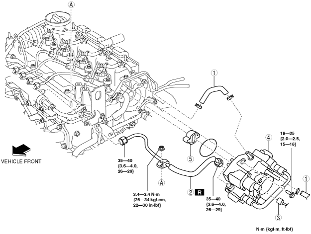
8. Remove in the order indicated in the table.
9. Install in the reverse order of removal.
10. Complete the “AFTER SERVICE PRECAUTION”. (See AFTER SERVICE PRECAUTION [MZR-CD 2.2].)
am3zzw00012092
|
|
1
|
Fuel hose
(See Fuel Hose Installation Note.)
|
|
2
|
Injection pipe (supply pump side)
|
|
3
|
Suction control valve connector
|
|
4
|
Supply pump
|
|
5
|
Spacer
|
Supply Pump Installation Note
1. Visually inspect the O-ring.
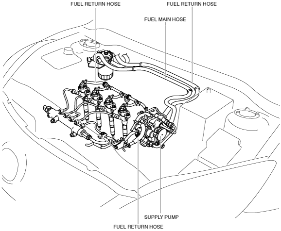
Fuel Hose Installation Note
1. Install the fuel main hose and fuel return hose as shown in the figure.
L.H.D.
am3zzw00005546
|
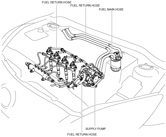
R.H.D.
am3zzw00005547
|
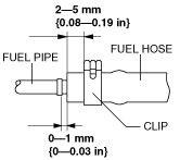
2. Fit the fuel pipe onto the respective fittings, and install clamps as shown.
am6zzw00004268
|