 |
am3zzw00012030
INTAKE-AIR SYSTEM REMOVAL/INSTALLATION [MZR-CD 2.2]
id0113f3801900
MAF sensor
|
STEP |
ACTION |
PAGE/CONDITION |
|---|---|---|
|
1
|
Replace the MAF/IAT sensor.
|
–
|
|
2
|
Switch the ignition to on.
|
–
|
|
3
|
Perform mass air flow (MAF) sensor data reset procedure.
|
|
|
4
|
Start the engine.
|
Verify that the MIL dose not illuminate.
|
|
5
|
Switch the ignition to off (Engine off).
|
–
|
|
6
|
Perform KOEO self-test procedure.
|
|
|
7
|
Switch the ignition to off.
|
–
|
|
8
|
Wait for 20 s.
|
–
|
|
9
|
Start the engine.
|
–
|
|
10
|
Perform KOER self-test procedure.
|
Warm up until the exhaust gas temperature (EXHTEMP1, EXHTEMP2 PID) is 100 °C {212 °F} or more.
|
|
11
|
Switch the ignition to off.
|
–
|
Intake shutter valve
|
STEP |
ACTION |
PAGE/CONDITION |
|---|---|---|
|
1
|
Replace the intake shutter valve.
|
–
|
|
2
|
Start the engine.
|
Verify that the MIL dose not illuminate.
|
|
3
|
Switch the ignition to off (Engine off).
|
–
|
|
4
|
Perform KOEO self-test procedure.
|
|
|
5
|
Perform intake shutter valve/EGR valve initialization procedure.
|
Engine coolant temperature 60—95 °C {140—203 °F}.
|
|
6
|
Switch the ignition to off.
|
–
|
|
7
|
Wait for 20 s.
|
–
|
|
8
|
Start the engine.
|
–
|
|
9
|
Perform KOER self-test procedure.
|
Warm up until the exhaust gas temperature (EXHTEMP1, EXHTEMP2 PID) is 100 °C {212 °F} or more.
|
|
10
|
Switch the ignition to off.
|
–
|
1. Complete the “BEFORE SERVICE PRECAUTION”. (See BEFORE SERVICE PRECAUTION [MZR-CD 2.2].)
2. Disconnect the negative battery cable. (See BATTERY REMOVAL/INSTALLATION [MZR-CD 2.2].)
3. Remove the engine cover. (See ENGINE COVER REMOVAL/INSTALLATION [MZR-CD 2.2].)
4. Remove in the order indicated in the table.
5. Install in the reverse order of removal.
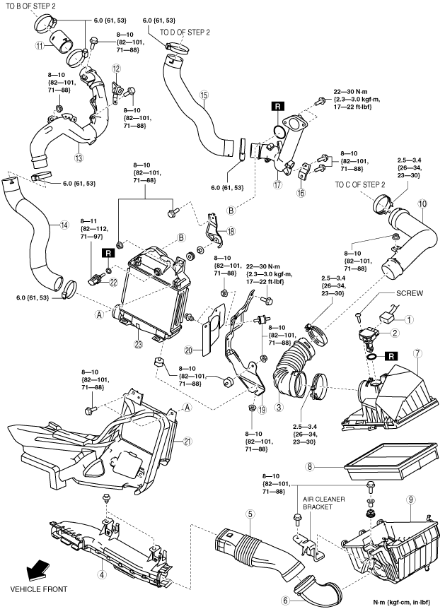
Step 1
am3zzw00012030
|
|
1
|
MAF/IAT sensor connector
|
|
2
|
MAF/IAT sensor
|
|
3
|
Air inlet hose
|
|
4
|
Fresh-air duct No.1
|
|
5
|
Fresh-air duct No.2
|
|
6
|
Fresh-air duct No.3
|
|
7
|
Air cleaner cover
|
|
8
|
Air cleaner element
|
|
9
|
Air cleaner case
|
|
10
|
Air inlet pipe
|
|
11
|
Turbocharger air outlet hose
(See Clamp Installation Note.)
|
|
12
|
Turbocharger air outlet pipe No.2 bracket
|
|
13
|
Turbocharger air outlet pipe No.2
|
|
14
|
Charge air cooler air inlet hose
(See Clamp Installation Note.)
|
|
15
|
Charge air cooler air outlet hose
(See Clamp Installation Note.)
|
|
16
|
Charge air cooler air outlet pipe bracket No.1
|
|
17
|
Charge air cooler air outlet pipe
|
|
18
|
Charge air cooler bracket No.1
|
|
19
|
Charge air cooler bracket No.2
|
|
20
|
Charge air cooler cover
|
|
21
|
Charge air cooler duct
|
|
22
|
IAT sensor No.2
|
|
23
|
Charge air cooler
|
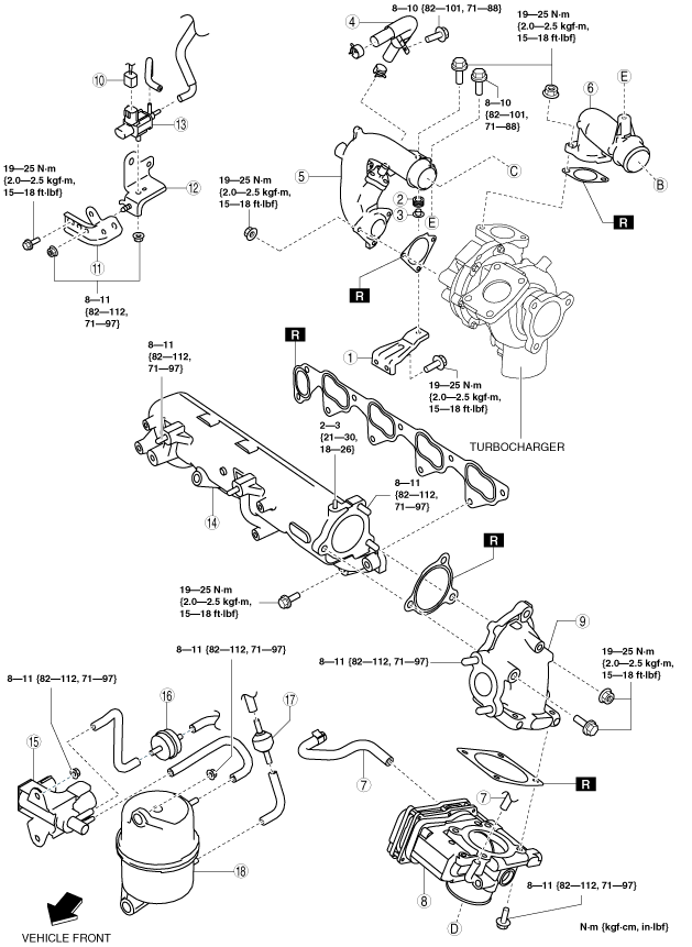
Step 2
am3zzw00012031
|
|
1
|
Turbocharger air inlet pipe bracket
|
|
2
|
Rubber
|
|
3
|
Spacer
|
|
4
|
Ventilation hose
|
|
5
|
Turbocharger air inlet pipe
|
|
6
|
Turbocharger air outlet pipe No.1
|
|
7
|
Water hose
(See Water Hose Removal Note.)
|
|
8
|
Intake shutter valve
|
|
9
|
Air intake elbow
|
|
10
|
EGR cooler bypass valve control solenoid valve connector
|
|
11
|
EGR cooler bypass valve control solenoid valve bracket No.1
|
|
12
|
EGR cooler bypass valve control solenoid valve bracket No.2
|
|
13
|
EGR cooler bypass valve control solenoid valve
|
|
14
|
Intake manifold
(See Intake Manifold Removal Note.)
|
|
15
|
VBC solenoid valve
|
|
16
|
Vacuum damper
|
|
17
|
VBC check valve
|
|
18
|
Vacuum chamber
|
Charge Air Cooler Air Inlet Hose Removal Note
1. Remove the aerodynamic under cover No.2. (See AERODYNAMIC UNDER COVER NO.2 REMOVAL/INSTALLATION.)
2. Remove the charge air cooler air inlet hose.
Charge Air Cooler Air Outlet Pipe Removal Note
1. Set the front mudguard (LH) out of the way. (See FRONT MUDGUARD REMOVAL/INSTALLATION.)
2. Remove the charge air cooler air outlet pipe.
Charge Air Cooler Duct Removal Note
1. Remove the front bumper. (See FRONT BUMPER REMOVAL/INSTALLATION.)
2. Remove the charge air cooler duct.
Intake Shutter Valve Removal Note
1. Remove the EGR pipe. (See EGR VALVE REMOVAL/INSTALLATION [MZR-CD 2.2].)
2. Remove the intake shutter valve.
Water Hose Removal Note
1. Drain the engine coolant. (See ENGINE COOLANT REPLACEMENT [MZR-CD 2.2].)
2. Disconnect the water hose.
Air Intake Elbow Removal Note
1. Set the fuel return pipe out of the way.
2. Remove the injection pipe (supply pump side). (See SUPPLY PUMP REMOVAL/INSTALLATION [MZR-CD 2.2].)
3. Remove the air intake elbow.
EGR Cooler Bypass Valve Control Solenoid Valve Bracket No.1 Removal Note
1. Remove the EGR cooler bypass valve control solenoid valve bracket No.1, EGR cooler bypass valve control solenoid valve bracket No.2 and EGR cooler bypass valve control solenoid valve as a single unit.
2. Remove the EGR cooler bypass valve control solenoid valve bracket No.1.
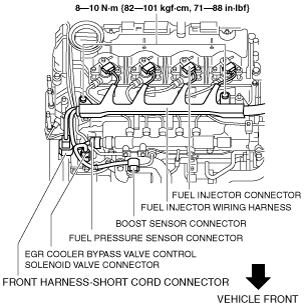
Intake Manifold Removal Note
1. Disconnect the following parts and set the fuel injector wiring harness out of the way.
am3zzw00012032
|
2. Remove the injection pipe (fuel injector side). (See FUEL INJECTOR REMOVAL/INSTALLATION [MZR-CD 2.2].)
3. Remove the dipstick pipe. (See CYLINDER HEAD GASKET REPLACEMENT [MZR-CD 2.2].)
4. Remove the boost sensor and the common rail. (See COMMON RAIL REMOVAL/INSTALLATION [MZR-CD 2.2].)
5. Remove the glow cord and the glow plug. (See GLOW PLUG REMOVAL/INSTALLATION [MZR-CD 2.2].)
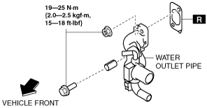
6. Disconnect the water hose.
7. Remove the water outlet pipe.
am3zzw00012033
|
8. Set the generator out of the way. (See GENERATOR REMOVAL/INSTALLATION [MZR-CD 2.2].)
9. Remove the battery and battery tray. (See BATTERY REMOVAL/INSTALLATION [MZR-CD 2.2].)
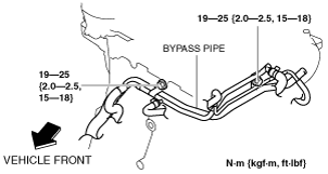
10. Loosen the bypass pipe installation bolts.
am3zzw00012034
|
11. Remove the intake manifold.
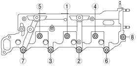
Intake Manifold Installation Note
1. Tighten the intake manifold installation bolts and nuts in the order shown.
am3zzw00010052
|
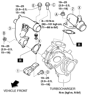
Turbocharger Air Inlet Pipe Bracket, Turbocharger Air Inlet Pipe, Turbocharger Air Outlet Pipe No.1 Installation Note
1. Temporary tighten in the order shown in the figure.
am3zzw00012035
|
2. Tighten the nut A.
3. Tighten the nut B.
4. Tighten the bolt C.
5. Tighten the bolt D.
6. Tighten the bolt E.
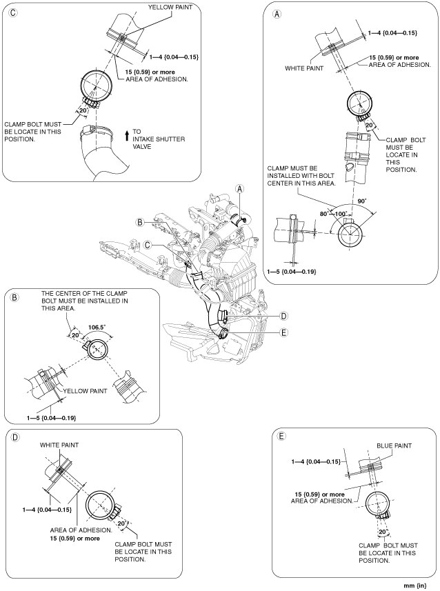
Clamp Installation Note
1. Install the clamp as shown in the figure.
am3zzw00005540
|