EXHAUST GAS PRESSURE SENSOR INSPECTION [MZR-CD 2.2]


id0140f2446000

Note
•  Perform the following test only when directed.

Voltage Inspection

Caution
•  Because the output characteristics of the exhaust gas pressure sensor/exhaust gas pressure correction temperature sensor are adjusted while it is installed to the bracket, replace the exhaust gas pressure sensor/exhaust gas pressure correction temperature sensor and the bracket as a single unit.

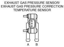
1.  While the connector is connected, remove the hoses attached to exhaust gas pressure sensor/exhaust gas pressure correction temperature sensor ports A and B.

am3zzw00011590

2.  Switch the ignition to ON.

3.  Verify that the voltage at the PCM terminal 1AD is within the specification.

Specification
1.04.5 V
•  If as specified, then go to the next step.
•  If not as specified, replace the exhaust gas pressure sensor/exhaust gas pressure correction temperature sensor and the bracket as a single unit. (See EXHAUST GAS PRESSURE SENSOR/EXHAUST GAS PRESSURE CORRECTION TEMPERATURE SENSOR REMOVAL/INSTALLATION [MZR-CD 2.2].)

4.  Verify that the voltage variance at the PCM terminal 1AD is within the specification when a pressure of 0—100 kPa {0.00—1.01 kgf/cm2, 0.0—14.5 psi} is applied to exhaust gas pressure sensor/exhaust gas pressure correction temperature sensor port A.

Voltage variance
1.04.5 V
•  If not as specified, replace the exhaust gas pressure sensor/exhaust gas pressure correction temperature sensor and the bracket as a single unit. (See EXHAUST GAS PRESSURE SENSOR/EXHAUST GAS PRESSURE CORRECTION TEMPERATURE SENSOR REMOVAL/INSTALLATION [MZR-CD 2.2].)