|
am3zzw00011601
INTAKE AIR TEMPERATURE (IAT) SENSOR INSPECTION [MZR-CD 2.2]
id0140f2802200
IAT Sensor
Resistance inspection
1. Disconnect the negative battery cable. (See BATTERY REMOVAL/INSTALLATION [MZR-CD 2.2].)
2. Disconnect the MAF/IAT sensor connector. (See INTAKE-AIR SYSTEM REMOVAL/INSTALLATION [MZR-CD 2.2].)
3. Measure the resistance between MAF/IAT sensor terminals D and E.
am3zzw00011601
|
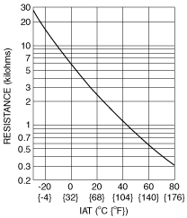
Specification
|
IAT (°C {°F}) |
Resistance (kilohms) |
|---|---|
|
−20 {−4}
|
13.6—18.4
|
|
20 {68}
|
2.21—2.69
|
|
60 {140}
|
0.493—0.667
|
IAT sensor characteristics graph (Reference)
am3zzw00011602
|
IAT Sensor No.2
Visual inspection
1. Disconnect the negative battery cable. (See BATTERY REMOVAL/INSTALLATION [MZR-CD 2.2].)
2. Remove the engine cover. (See ENGINE COVER REMOVAL/INSTALLATION [MZR-CD 2.2].)
3. Disconnect the IAT sensor No.2 connector.
4. Remove the IAT sensor No.2. (See INTAKE-AIR SYSTEM REMOVAL/INSTALLATION [MZR-CD 2.2].)
5. Visually inspect the IAT sensor No.2 for the following:
Resistance inspection
1. Disconnect the negative battery cable. (See BATTERY REMOVAL/INSTALLATION [MZR-CD 2.2].)
2. Remove the engine cover. (See ENGINE COVER REMOVAL/INSTALLATION [MZR-CD 2.2].)
3. Disconnect the IAT sensor No.2 connector.
4. Remove the IAT sensor No.2. (See INTAKE-AIR SYSTEM REMOVAL/INSTALLATION [MZR-CD 2.2].)
5. Place the IAT sensor No.2 in water with a thermometer, and heat the water gradually.
6. Measure the resistance between IAT sensor No.2 terminals A and B.
am3zzw00011603
|
Specification
|
Water temperature (°C {°F}) |
Resistance (kilohms) |
|---|---|
|
20 {68}
|
2.21—2.69
|
|
80 {176}
|
0.29—0.35
|