 |
am3zzn00003359
DRIVE-BY-WIRE CONTROL [SKYACTIV-G 2.0]
id0140f4188400
Outline
Control Table
|
Control name |
Control outline |
|---|---|
|
Idle air control
|
• While idling, the throttle valve opening is controlled so that the idle speed is at the target idle speed.
|
|
Accelerator control
|
• The throttle valve opening angle is controlled according to the amount the accelerator pedal is depressed. In addition, there is a fully closed learning function for learning deterioration over time and constant correction of the optimum throttle opening angle.
|
|
Traction control
|
• The throttle valve opening angle is controlled by the torque reduction request signal from the DSC HU/CM and TCM.
|
|
Excess engine speed control
|
• If the engine reaches a high engine speed, the throttle valve opening angle is controlled to protect the engine.
|
|
Overspeed control
|
• If the vehicle reaches a high speed, the throttle valve is closed to keep the vehicle speed below the speed limit.
|
|
Electric variable valve timing cooperation control
|
• Pumping loss is reduced by controlling the throttle valve timing opening angle according to the phase of the intake valve timing.
|
|
Cruise control (With cruise control system)
|
• Sets the vehicle speed by operation of the cruise control switch and controls the throttle valve opening angle so that it becomes close to the set vehicle speed.
|
|
Brake override system
|
• If the brake pedal is depressed with the accelerator pedal depressed, the vehicle can be stopped safely by closing the throttle valve. As a result, the brake operation takes priority over the accelerator pedal operation.
|
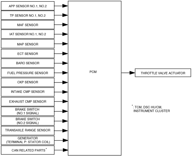
Block Diagram
am3zzn00003359
|
Operation
Idle air control
Correction list
|
Correction |
Purpose |
Vehicle condition |
Correction amount |
|---|---|---|---|
|
Engine coolant temperature correction
|
Corrects the fluctuation in engine sliding resistance due to change in engine temperature.
|
Correction amount is determined according to engine coolant temperature.
|
Low engine coolant temperature→large correction
|
|
Start correction
|
Prevents decrease in idle speed during engine start.
|
Immediately after cranking and engine start
|
Low engine coolant temperature→large correction
|
|
Feedback correction
|
Sets idle speed close to target engine speed.
|
• When all of the following conditions are met, feedback correction is performed.
|
Actual idle speed
Target engine speed or less→volume increase correction
Target engine speed or more→volume decrease correction
|
|
Learning correction
|
Corrects the changes in the air flow amount caused by engine deterioration over time such as engine sliding resistance and air leakage from the throttle valve.
|
Correction amount is determined according to the feedback correction amount while external load correction and purge control are stopped.
|
If the maximum or minimum value of feedback correction exceeds the specified value, learning correction is performed.
|
|
Evaporative purge correction
|
Air increased by purge control is subtracted from the target throttle opening angle.
|
Correction amount is determined according to purge flow amount during purge control execution.
|
Large purge flow amount→small correction
|
|
External load correction
|
• Prevents decrease in engine speed due to A/C and electrical load operation.
• Prevents sudden increase in engine rotation due to A/C and electrical load operation stop.
|
• When any of the following signals is input:
|
Large external load→large correction
|
|
Fast idle increase correction*
|
Activates the catalytic converter earlier after starting cold engine.
|
Integrates warm-up promotion spark retard correction for ignition timing control. (See ELECTRONIC SPARK ADVANCE CONTROL [SKYACTIV-G 2.0].)
|
Warm-up promotion spark retard for ignition timing control large→large correction
|
|
Hot engine restart correction
|
Prevents decrease in idle speed due to hot engine restart.
|
Just after cranking and engine start when the engine coolant temperature is 60 °C {140 °F} or more and intake air temperature is 50 °C {122 °F} or more.
|
High intake airflow temperature→large correction
|
|
D-range correction
|
Prevents decrease in idle speed due to shifting into D-range
|
When D range signal (transaxle range sensor) is input
|
Large D range load→large correction
|
Accelerator control
Traction control
Excess engine speed control
Overspeed control
Electric variable valve timing cooperation control
Cruise Control (With Cruise Control System)
Function List
|
Function |
Contents |
|---|---|
|
Accelerating
|
• When any of the following conditions are met while driving in cruise control and when the SET+ switch is continuously pressed, the PCM gradually increases the set vehicle speed.
|
|
Coasting
|
• When the SET- switch is continuously pressed, the PCM gradually decreases the set vehicle speed.
|
|
Resume
|
• When the RESUME switch signal is input to the PCM during regular driving (cruise control is stopped) and the previously set vehicle speed is stored in the PCM, the PCM sets the set vehicle speed to the previously set vehicle speed and begins control.
|
|
Tap down
|
• When all of the following conditions are met while driving in cruise control, the PCM decreases the set vehicle speed by 1.6 km/h {0.99 mph}.
|
|
Tap-up
|
• When all of the following conditions are met, the PCM increases the set vehicle speed by 1.6 km/h {0.99 mph}.
|
|
Downshift
|
• When the following conditions are met, a downshift signal is sent to the TCM (ATX) via CAN.
|
Brake override system
|
Operation start conditions
|
• If either one of the following conditions is met with the brake pedal depressed for the specified time*1 or more while the accelerator pedal is depressed, the PCM adjusts the throttle valve opening angle so that the engine speed is at specification*2.
While driving vehicle
While vehicle stopped
|
|
Operation complete conditions
|
• If the following conditions are met while operating the brake override system, the PCM stops the operation of the brake override system and controls the throttle valve opening angle in accordance with the accelerator pedal opening angle.
|
|
Cancel conditions
|
• If the releasing procedure is implemented with the following conditions met within 30 s after switching the ignition ON (KOEO), the brake override system does not operate until the recovery condition is met.
|
|
Recovery condition
|
• The cancel conditions are reset when the ignition is switched off while the brake override system is canceled. As a result, the brake override system can operate.
|