|
am3zzw00013261
REAR UPPER ARM REMOVAL/INSTALLATION
id021400800800
1. Remove in the order indicated in the table.
2. Install in the reverse order of removal.
3. Inspect the wheel alignment and adjust it if necessary. (See REAR WHEEL ALIGNMENT.)
am3zzw00013261
|
|
1
|
Rear stabilizer control link upper side nut
|
|
2
|
Rear upper arm
(See Rear Upper Arm Removal Note.)
|
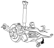
Rear Stabilizer Control Link Upper Part Removal Note
1. Disconnect the rear stabilizer control link upper part.
2. Rotate the rear stabilizer as shown in the figure.
azzzcw00000089
|
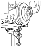
Rear Upper Arm Removal Note
1. Jack up the vehicle to the unloaded condition, and support the rear trailing link using a jack.
am3uuw00002883
|
2. Remove the rear upper arm.
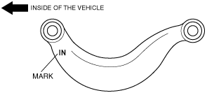
Rear Upper Arm Installation Note
1. Install the rear upper arm so that IN mark is facing toward the inside of the vehicle.
am3uuw00000890
|
Rear Stabilizer Control Link Upper Side Nut Installation Note
1. Verify the shape of the removed nut and if it is an A type, replace the nut with a new one.
azzzcw00000090
|
2. Install and tighten the nut.
azzzcw00000090
|