 |
am3zzw00011418
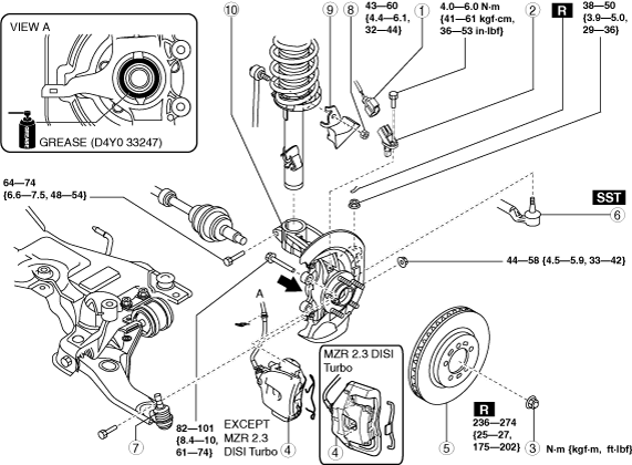
WHEEL HUB, STEERING KNUCKLE REMOVAL/INSTALLATION
id031100800400
1. Remove in the order indicated in the table.
2. Install in the reverse order of removal.
3. After installation, inspect the front wheel alignment and adjust it if necessary. (See FRONT WHEEL ALIGNMENT.)
am3zzw00011418
|
|
1
|
ABS wheel-speed sensor connector
|
|
2
|
ABS wheel-speed sensor
|
|
3
|
Locknut
|
|
4
|
Brake caliper component
|
|
5
|
Disc plate
|
|
6
|
Tie-rod end ball joint
|
|
7
|
Front lower arm ball joint
|
|
8
|
Stabilizer control link upper nut
|
|
9
|
Dynamic damper
|
|
10
|
Wheel hub, steering knuckle component
|
Brake Caliper Component Removal Note
1. Remove the retaining clip, mounting support installing bolt and suspend it out of the way using a cable.
am3uuw00004690
|
Wheel Hub, Steering Knuckle Component Removal Note
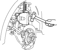
1. Separate the shock absorber from the wheel hub, steering knuckle component by tapping the upper part of the steering knuckle with a hammer.
am3uuw00004691
|
Wheel Hub, Steering Knuckle Component Installation Note
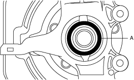
1. Apply grease (D4Y0 33247) to the wheel bearing inner race and drive shaft contact surface (Area A in figure).
am3zzw00008765
|
2. Install the wheel hub, steering knuckle component.
Front Lower Arm Ball Joint Installation Note