 |
am3zzw00011231
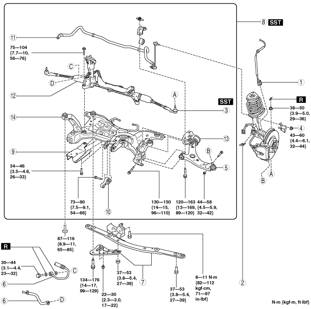
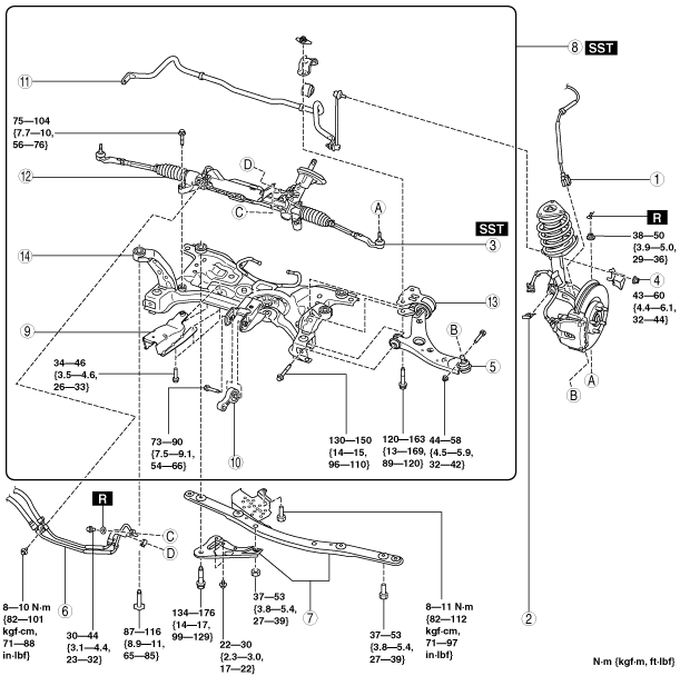
FRONT CROSSMEMBER REMOVAL/INSTALLATION [MZR 2.0 DISI i-stop, SKYACTIV-G 2.0]
id0213008010e2
1. Remove the joint cover. (See \nSTEERING WHEEL AND COLUMN REMOVAL/INSTALLATION [WITHOUT ADVANCED KEYLESS ENTRY AND PUSH BUTTON START SYSTEM].) (See \nSTEERING WHEEL AND COLUMN REMOVAL/INSTALLATION [WITH ADVANCED KEYLESS ENTRY AND PUSH BUTTON START SYSTEM].)
2. Disconnect the steering shaft from the steering gear and linkage. (See \nSTEERING WHEEL AND COLUMN REMOVAL/INSTALLATION [WITHOUT ADVANCED KEYLESS ENTRY AND PUSH BUTTON START SYSTEM].) (See \nSTEERING WHEEL AND COLUMN REMOVAL/INSTALLATION [WITH ADVANCED KEYLESS ENTRY AND PUSH BUTTON START SYSTEM].)
3. Remove in the order indicated in the table.
4. Install in the reverse order of removal.
5. Inspect the wheel alignment and adjust it if necessary. (See \nFRONT WHEEL ALIGNMENT.)
MZR 2.0 DISI i-stop
am3zzw00011231
|
SKYACTIV-G 2.0
am3zzw00010888
|
|
1
|
Front ABS wheel-speed sensor wiring harness connector
|
|
2
|
Brake hose clip
|
|
3
|
Tie-rod end ball joint
|
|
4
|
Front stabilizer control link upper nut
|
|
5
|
Front lower arm ball joint
|
|
6
|
Power steering pipe component
|
|
7
|
Front crossmember bracket
|
|
8
|
Front crossmember component
|
|
9
|
Bracket
|
|
10
|
No.1 engine mount rubber
|
|
11
|
Front stabilizer
|
|
12
|
Steering gear and linkage
|
|
13
|
Front lower arm
(See \nFRONT LOWER ARM REMOVAL/INSTALLATION.)
|
|
14
|
Front crossmember
|
Tie-rod End Ball Joint Removal Note
1. Detach the tie-rod end from the steering knuckle using the SST.
am3uuw00000421
|
Front Crossmember Bracket Removal Note (SKYACTIV-G 2.0)
1. Disconnect the wiring harness connecting to the front crossmember bracket.
am3uuw00007787
|
Front Crossmember Component Removal Note
1. Support the front crossmember component using a jack.
am3uuw00000422
|
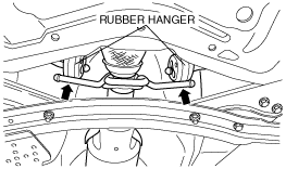
2. Detach the rubber hangers from the front crossmember.
am3uuw00002826
|
3. Detach the No.1 engine mounting from the engine.
4. Remove the front crossmember installation bolts.
5. Remove the front crossmember, front stabilizer, front lower arm, and steering gear and linkage as a single unit.
No. 1 Engine Mount Rubber and Front Crossmember Component Installation Note
1. Temporarily install the No.1 engine mount rubber to the front crossmember.
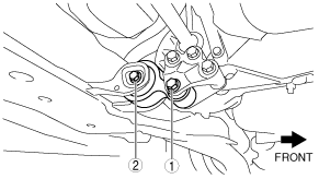
2. Verify the left and right identification marks and install the positioning SSTs to the front crossmember.
am3uuw00002827
|
3. Temporarily tighten the No.1 engine mount rubber to the front crossmember.
4. Raise the transmission jack gradually and install the front crossmember to the vehicle. At this point verify that the SSTs is securely inserted in the positioning holes on the body.
am3uuw00003444
|
5. Tighten the front crossmember installation bolts and nuts.
6. Tighten the bolts in the order shown in the figure.
MZR 2.0 DISI i-stop
am3zzw00010886
|
SKYACTIV-G 2.0
am3zzw00010889
|
Front Lower Arm Ball Joint Installation Note