 |
am3zzw00010582
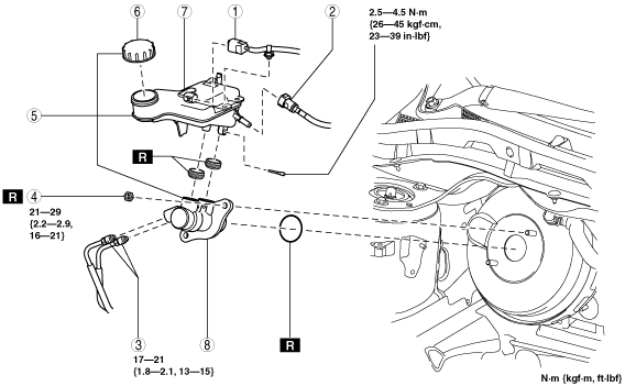
MASTER CYLINDER REMOVAL/INSTALLATION [MZR 2.3 DISI Turbo]
id0411008013p3
1. Remove the battery and battery tray. (L.H.D.) (See BATTERY REMOVAL/INSTALLATION [MZR 2.3 DISI Turbo].)
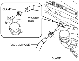
2. Pinch open the clamp using pliers and disconnect the vacuum hose from the insulator bracket as shown in the figure. (L.H.D.)
am3zzw00010582
|
3. For R.H.D., remove the following parts:
4. Remove in the order indicated in the table.
5. Install in the reverse order of removal.
L.H.D.
am3uuw00005754
|
|
1
|
Nut
|
|
2
|
Insulator
|
|
3
|
Brake fluid level sensor connector
|
|
4
|
Reserve hose
(See Reserve Hose Removal Note.)
|
|
5
|
Brake pipe
|
|
6
|
Nut
|
|
7
|
Insulator bracket
|
|
8
|
Master cylinder
|
|
9
|
Cap
|
|
10
|
Reserve tank
|
|
11
|
Cylinder component
|
R.H.D.
am3zzw00008585
|
|
1
|
Brake fluid level sensor connector
|
|
2
|
Reserve hose
(See Reserve Hose Removal Note.)
|
|
3
|
Brake pipe
|
|
4
|
Nut
|
|
5
|
Master cylinder
|
|
6
|
Cap
|
|
7
|
Reserve tank
|
|
8
|
Cylinder component
|
Reserve Hose Removal Note
1. Remove the reserve hose from the reserve tank while pressing the point indicated by the arrow in the figure.
am3zzw00008586
|
Insulator Bracket, Master Cylinder Removal Note (L.H.D.)
1. Remove the insulator bracket and master cylinder from the power brake unit as a single unit.
2. Remove the insulator bracket from the master cylinder.
Master Cylinder, Insulator Bracket Installation Note (L.H.D.)
1. Temporarily install the insulator bracket to the master cylinder.
2. Install the insulator bracket and master cylinder to the power brake unit as a single unit.
Reserve Hose Installation Note
1. Insert the reserve hose to the reserve tank until a click is heard.
2. Verify that the reserve hose is firmly installed by pulling it, and push it into the reserve tank again.