 |
am3uuw00002613
ON-BOARD DIAGNOSTIC SYSTEM DTC INSPECTION [FS5A-EL]
id050221290100
Reading DTCs Procedure
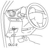
1. Connect the M-MDS (IDS) to the DLC-2.
am3uuw00002613
|
2. After the vehicle is identified, select the following items from the initialization screen of the IDS.
3. Verify the DTC according to the directions on the IDS screen.
Freeze frame data table
|
Freeze frame data item |
Unit |
Description |
Corresponding PID data monitor item |
|---|---|---|---|
|
LOAD
|
%
|
Calculated engine load
|
—
|
|
ECT
|
°C {°F}
|
Engine coolant temperature
|
ECT
|
|
RPM
|
RPM
|
Engine speed
|
RPM
|
|
VS
|
KPH {MPH}
|
Vehicle speed
|
VSS
|
|
SPARKADV
|
°
|
Ignition timing
|
—
|
|
IAT
|
°C {°F}
|
Intake air temperature
|
—
|
|
TP
|
%
|
Throttle valve position No.1
|
THOP
|
|
RUNTM
|
hh:mm:ss
|
Time from engine start
|
—
|
|
WARMUPS
|
—
|
Number of warm-up cycle after DTC cleared
|
—
|
|
CLRDIST
|
Km {mile}
|
Mileage after DTC cleared
|
—
|
|
VPWR
|
V
|
Module supply voltage
|
VPWR
|
|
APP_D
|
%
|
Accelerator pedal position No.1
|
—
|
Snapshot data table
|
Snapshot data item |
Unit |
Definition |
Corresponding PID data monitor item |
|---|---|---|---|
|
LOAD
|
%
|
Calculated engine load
|
—
|
|
ECT
|
°C {°F}
|
Engine coolant temperature
|
ECT
|
|
RPM
|
RPM
|
Engine speed
|
RPM
|
|
VSS
|
KPH {MPH}
|
Vehicle speed
|
VSS
|
|
SPARKADV
|
°
|
Ignition timing
|
—
|
|
IAT
|
°C {°F}
|
Intake air temperature
|
—
|
|
TP1
|
%
|
Throttle valve position No.1
|
THOP
|
|
EG_RUN_TIME
|
—
|
Time from engine start
|
—
|
|
CLR_CNT
|
—
|
Number of warm-up cycle after DTC cleared
|
—
|
|
CLR_DIST
|
Km {mile}
|
Mileage after DTC cleared
|
—
|
|
VPWR
|
V
|
Module supply voltage
|
VPWR
|
|
APP1
|
%
|
Accelerator pedal position No.1
|
—
|
Clearing DTCs Procedure
1. Connect the M-MDS (IDS) to the DLC-2.
am3uuw00002613
|
2. After the vehicle is identified, select the following items from the initialization screen of the IDS.
3. Verify the DTC according to the directions on the IDS screen.
4. Press the clear button on the DTC screen to clear the DTC.