 |
am3uuw00002614
ON-BOARD DIAGNOSTIC SYSTEM PID/DATA MONITOR INSPECTION [FS5A-EL]
id050221290300
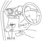
1. Connect the M-MDS (IDS) to the DLC-2.
am3uuw00002614
|
2. After the vehicle is identified, select the following items from the initialization screen of the IDS.
3. Select the applicable PID from the PID table.
4. Verify the PID data according to the detections on the screen.
PID/DATA Monitor Table (Reference)
|
Monitor item |
Unit/Condition |
Test condition |
Specification |
Inspection item |
|---|---|---|---|---|
|
DGP_DIS_1
|
km {mile}
|
This PID indicates the traveled distance since DTC P1712:00 was last recorded.
|
||
|
DGP_DIS_2
|
km {mile}
|
This PID indicates the traveled distance since the maximum rotation speed difference occurred between the left and right drive wheels.
|
||
|
DGP_MAX_DIF
|
RPM
|
This PID indicates the maximum rotation speed difference between the left and right drive wheels.
|
||
|
DGP_SPD
|
KPH {MPH}
|
This PID Indicates the vehicle speed with the trailing wheels at the time the maximum rotation speed difference between the left and right drive wheels occurred.
|
||
|
DWN SW
|
On/Off
|
Selector lever at shift down position
|
On
|
• Down switch
• Related harness
|
|
Except selector lever at shift down position
|
Off
|
|||
|
ECT
|
°C {°F}
|
ECT 20°C {68°F}
|
Approx.20°C {68°F}
|
• PCM
|
|
GEAR_RA
|
—
|
1GR
|
Approx.3.620
|
• Following PIDs:
|
|
2GR
|
Approx.1.925
|
|||
|
3GR
|
Approx.1.285
|
|||
|
4GR
|
Approx.0.933
|
|||
|
5GR
|
Approx.0.692
|
|||
|
GEAR_SEL
|
1st/2nd/3rd/4th/5th
|
1GR
|
1st
|
• Following PIDs:
|
|
2GR
|
2nd
|
|||
|
3GR
|
3rd
|
|||
|
4GR
|
4th
|
|||
|
5GR
|
5th
|
|||
|
HTM_CNT
|
—
|
This PID indicates number of high oil temperature mode operations.
High oil temperature mode is switched when ATF reaches approx.130 °C {266 °F} or more.
|
||
|
HTM_DIS
|
km {mile}
|
This PID indicates travel distance after operation of high oil temperature mode.
High oil temperature mode is switched when ATF reaches approx.130 °C {266 °F} or more.
|
||
|
ISS
|
RPM
|
Vehicle stopped
|
0 RPM
|
• Intermediate sensor
• Related harness
|
|
Vehicle speed 30 km/h {19 mph} in 3GR
|
Approx.1,300 RPM (MZR 2.0) / Approx.1,200 RPM (MZR 2.5)
|
|||
|
LINEDES
|
Pa {kgf/cm2, psi}
|
Idle at P position after warm-up
|
Approx.400 kPa {4.08 kgf/cm2, 58.0 psi}
|
• Following PIDs:
|
|
Engine speed 2,000 rpm at P position
|
Approx.560 kPa {5.71 kgf/cm2, 81.2psi}
|
|||
|
LPS
|
A
|
Idle at P position after warm-up
|
Approx.950 mA
|
• Pressure control solenoid A
• Related harness
|
|
Engine speed 2,000 rpm at P position
|
Approx.830 mA
|
|||
|
LPSB
|
%
|
Gear shifting from 4GR to 5GR
|
Approx.100%
|
• Pressure control solenoid B
• Related harness
|
|
Gear shifting from 5GR to 4GR
|
Approx.50%
|
|||
|
Other conditions
|
0%
|
|||
|
MNL SW
|
On/Off
|
Selector lever at P position
|
Off
|
• M range switch
• Related harness
|
|
Selector lever at R position
|
Off
|
|||
|
Selector lever at N position
|
Off
|
|||
|
Selector lever at D range
|
Off
|
|||
|
Selector lever at M range
|
On
|
|||
|
OP_SW_B
|
On/Off
|
1GR
|
On
|
• Oil pressure switch
• Related harness
|
|
2GR
|
On
|
|||
|
3GR
|
On
|
|||
|
4GR
|
Off
|
|||
|
5GR
|
Off
|
|||
|
OSS
|
RPM
|
Vehicle stopped
|
0 RPM
|
• VSS
• Related harness
|
|
Vehicle speed 30 km/h {19 mph} in 3GR
|
Approx.250 RPM
|
|||
|
RPM
|
RPM
|
Engine speed 1,000 rpm
|
Approx.1,000 RPM
|
• PCM
|
|
SSA/SS1
|
%
|
1GR at D range
|
0%
|
• Shift solenoid A
• Related harness
|
|
2GR at D range
|
0%
|
|||
|
3GR at D range
|
0%
|
|||
|
4GR at D range
|
Approx.100%
|
|||
|
5GR at D range
|
Approx.100%
|
|||
|
SSB/SS2
|
%
|
1GR at D range
|
Approx.100%
|
• Shift solenoid B
• Related harness
|
|
2GR at D range
|
0%
|
|||
|
3GR at D range
|
0%
|
|||
|
4GR at D range
|
0%
|
|||
|
5GR at D range
|
0%
|
|||
|
SSC/SS3
|
%
|
1GR at D range
|
Approx.100%
|
• Shift solenoid C
• Related harness
|
|
2GR at D range
|
Approx.100%
|
|||
|
3GR at D range
|
0%
|
|||
|
4GR at D range
|
0%
|
|||
|
5GR at D range
|
0%
|
|||
|
SSD/SS4
|
On/Off
|
1GR at D range
|
Off
|
• Shift solenoid D
• Related harness
|
|
2GR at D range
|
Off
|
|||
|
3GR at D range
|
Off
|
|||
|
4GR at D range
|
On
|
|||
|
5GR at D range
|
On
|
|||
|
SSE_SS5
|
On/Off
|
TCC released
|
Off
|
• Shift solenoid E
• Related harness
|
|
TCC engaged
|
On
|
|||
|
SSF_SS6
|
On/Off
|
1GR at D range
|
Off
|
• Shift solenoid F
• Related harness
|
|
2GR at D range
|
Off
|
|||
|
3GR at D range
|
Off
|
|||
|
4GR at D range
|
Off
|
|||
|
5GR at D range
|
On
|
|||
|
TFT
|
°C {°F}
|
ATF 20 °C {68°F}
|
Approx.20 °C {68°F}
|
• TFT sensor
• Related harness
|
|
ATF 65 °C {149°F}
|
Approx.65 °C {149°F}
|
|||
|
TFTV
|
V
|
ATF 20 °C {68°F}
|
Approx.3.3 V
|
• TFT sensor
• Related harness
|
|
ATF 65 °C {149°F}
|
Approx.1.3 V
|
|||
|
THOP
|
%
|
Accelerator pedal fully released
|
Approx.13%
|
• PCM
|
|
Accelerator pedal fully depressed
|
Approx.84%
|
|||
|
TR
|
P/R/N/D
|
Selector lever at P position
|
P
|
• TR switch
• Related harness
|
|
Selector lever at R position
|
R
|
|||
|
Selector lever at N position
|
N
|
|||
|
Selector lever at D range
|
D
|
|||
|
Selector lever at M range
|
D
|
|||
|
TR_SENS
|
V
|
Selector lever at P position
|
4.3—4.8
|
• TR switch
• Related harness
|
|
Selector lever at R position
|
3.8—4.2
|
|||
|
Selector lever at N position
|
3.0—3.5
|
|||
|
Selector lever at D range
|
2.2—2.7
|
|||
|
Selector lever at M range
|
2.2—2.7
|
|||
|
TSS
|
RPM
|
Engine speed 1,000 rpm at P position
|
Approx.950 RPM
|
• Input/turbine speed sensor
• Related harness
|
|
Vehicle stopped at D range
|
0 RPM
|
|||
|
UP SW
|
On/Off
|
Selector lever at shift up position
|
On
|
• Up switch
• Related harness
|
|
Except selector lever at shift up position
|
Off
|
|||
|
VPWR
|
V
|
Under any condition
|
B+
|
• Battery
• Related harness
|
|
VSS
|
KPH {MPH}
|
Vehicle stopped
|
Approx.0 KPH {0 MPH}
|
• VSS
• Related harness
|
|
Vehicle speed 30 km/h {19 MPH}
|
Approx.30 KPH {19 MPH}
|
|||