 |
am3zzw00012693
ON-BOARD DIAGNOSTIC SYSTEM DTC INSPECTION [FW6A-EL]
id050225290100
Reading DTCs Procedure
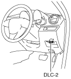
1. Connect the M-MDS (IDS) to the DLC-2.
am3zzw00012693
|
2. After the vehicle is identified, select the following items from the initialization screen of the IDS.
3. Then, select the "Retrieve CMDTCs” and perform procedures according to directions on the IDS screen.
4. Verify the DTC according to the directions on the screen.
5. After completion of repairs, clear all DTCs stored in the TCM. (See Clearing DTCs Procedures.)
Freeze frame data item table
|
Freeze frame data item |
Unit |
Description |
Corresponding PID/DATA monitor item |
|---|---|---|---|
|
LOAD
|
%
|
Calculated engine load
|
LOAD
|
|
ECT
|
°C {°F}
|
Engine coolant temperature
|
ECT
|
|
RPM
|
RPM
|
Engine speed
|
RPM
|
|
VS
|
KPH {MPH}
|
Vehicle speed
|
VSS
|
|
SPARKADV
|
°
|
Ignition timing
|
SPARKADV
|
|
IAT
|
°C {°F}
|
Intake air temperature
|
IAT
|
|
TP
|
%
|
Throttle valve position No.1
|
TP
|
|
RUNTM
|
hh:mm:ss
|
Time from engine start
|
—
|
|
VPWR
|
V
|
Module supply voltage
|
VPWR
|
|
APP_D
|
%
|
Accelerator pedal position No.1
|
APP1
|
Snapshot data item table
|
Snapshot data item |
Unit |
Description |
Corresponding PID/DATA monitor item |
|---|---|---|---|
|
LOAD
|
%
|
Calculated engine load
|
LOAD
|
|
ECT
|
°C {°F}
|
Engine coolant temperature
|
ECT
|
|
RPM
|
RPM
|
Engine speed
|
RPM
|
|
VSS
|
KPH {MPH}
|
Vehicle speed
|
VSS
|
|
IAT
|
°C {°F}
|
Intake air temperature
|
IAT
|
|
EG_RUN_TIME
|
—
|
Time from engine start
|
—
|
|
VPWR
|
V
|
Module supply voltage
|
VPWR
|
|
APP1
|
%
|
Accelerator pedal position No.1
|
APP1
|
|
GEAR_SEL
|
1/2/3/4/5/6
|
Gear shift position
|
GEAR_SEL
|
|
TSS
|
RPM
|
Turbine/input shaft speed
|
TSS
|
|
TFT
|
°C {°F}
|
ATF temperature
|
TFT
|
|
OSS
|
RPM
|
Output shaft speed
|
OSS
|
|
LOCK_UP
|
OFF/SLIP/On
|
Torque converter (TCC condition)
|
LOCK_UP
|
|
OIL_PRES_SW2
|
Off/On
|
Oil pressure switch No.2 condition
|
OP_SW2
|
|
OIL_PRES_SW1
|
Off/On
|
Oil pressure switch No.1 condition
|
OP_SW1
|
|
SS_ON_OFF
|
Off/On
|
On/off solenoid condition
|
SS_ON-OFF
|
|
APP
|
%
|
Accelerator pedal position No.1
|
APP1
|
|
G_INHIBIT_6
|
Off/On
|
6GR is inhibited due to malfunction.
|
—
|
|
G_INHIBIT_5
|
Off/On
|
5GR is inhibited due to malfunction.
|
—
|
|
G_INHIBIT_4
|
Off/On
|
4GR is inhibited due to malfunction.
|
—
|
|
G_INHIBIT_3
|
Off/On
|
3GR is inhibited due to malfunction.
|
—
|
|
G_INHIBIT_2
|
Off/On
|
2GR is inhibited due to malfunction.
|
—
|
|
G_INHIBIT_1
|
Off/On
|
1GR is inhibited due to malfunction.
|
—
|
|
G_INHIBIT_R
|
Off/On
|
R position is inhibited due to malfunction.
|
—
|
|
G_INHIBIT_N
|
Off/On
|
N position is inhibited due to malfunction.
|
—
|
|
OIL_PRES_SW4
|
Off/On
|
Oil pressure switch No.4 condition
|
OP_SW4
|
|
OIL_PRES_SW3
|
Off/On
|
Oil pressure switch No.3 condition
|
OP_SW3
|
|
EOP_RLY
|
Off/On
|
Electric AT oil pump relay condition
|
EOP_RLY
|
|
SHIFT_CTRL
|
DEFAULT/MANUAL/C_CONTROL/HIGH_TEMP/D_MANUAL/FAIL_SAFE
|
Shift control mode
|
SHIFT_CTRL
|
|
SLIP_VALUE
|
RPM
|
Actual slip value between TSS and OSS
|
—
|
|
HTM_DIS
|
km {mile}
|
Travel distance since determination of ATF high temperature mode
|
HTM_DIS
|
Clearing DTCs Procedures
1. Connect the M-MDS (IDS) to the DLC-2.
am3zzw00012693
|
2. After the vehicle is identified, select the following items from the initialization screen of the IDS.
3. Verify the DTC according to the directions on the screen.
4. Press the clear button on the DTC screen to clear the DTC.
5. Switch the ignition to off.
6. Switch the ignition to ON and wait for 5 s or more.
7. Perform DTC inspection. (See Reading DTCs Procedure.)
8. Verify that no DTCs are displayed.