 |
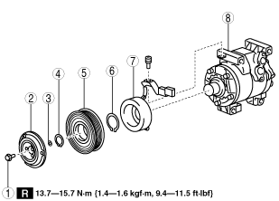
am3zzw00010988
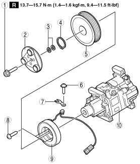
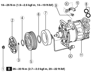
MAGNETIC CLUTCH DISASSEMBLY/ASSEMBLY [FULL-AUTO AIR CONDITIONER]
id0740a1800400
1. Disassemble in the order indicated in the table.
SKYACTIV-G 2.0
am3zzw00010988
|
|
1
|
Bolt
|
|
2
|
Pressure plate
|
|
3
|
Shim
(See Shim Installation Note.)
|
|
4
|
Snap ring
|
|
5
|
A/C compressor pulley
|
|
6
|
Snap ring
|
|
7
|
Stator
|
|
8
|
A/C compressor body
|
MZR 2.5, MZR 2.3 DISI Turbo
am3zzw00010989
|
|
1
|
Bolt
|
|
2
|
Pressure plate
|
|
3
|
Shim
(See Shim Installation Note.)
|
|
4
|
Snap ring
|
|
5
|
A/C compressor pulley
|
|
6
|
Snap ring
|
|
7
|
Stator
|
|
8
|
A/C compressor body
|
MZR 2.0, MZR 2.0 DISI i-stop
am3zzw00010990
|
|
1
|
Bolt
|
|
2
|
Pressure plate
|
|
3
|
Shim
(See Shim Installation Note.)
|
|
4
|
Snap ring
|
|
5
|
A/C compressor pulley
|
|
6
|
Snap ring
|
|
7
|
Stator
|
|
8
|
A/C compressor body
|
MZR 1.5, MZR 1.6
am3zzw00010991
|
|
1
|
Bolt
|
|
2
|
Pressure plate
|
|
3
|
Shim
(See Shim Installation Note.)
|
|
4
|
Snap ring
|
|
5
|
A/C compressor pulley
|
|
6
|
Screw
(See Screw Installation Note.)
|
|
7
|
Clamp
(See Clamp Installation Note.)
|
|
8
|
Screw
(See Screw Installation Note.)
|
|
9
|
Stator and thermal protector
|
|
10
|
A/C compressor body
|
MZ-CD 1.6
am3zzw00009996
|
|
1
|
Nut
|
|
2
|
Pressure plate
|
|
3
|
Shim
(See Shim Installation Note.)
|
|
4
|
Snap ring
|
|
5
|
A/C compressor pulley
|
|
6
|
Snap ring
|
|
7
|
Stator
|
|
8
|
O-ring
|
|
9
|
Bolt
|
|
10
|
Bracket
|
|
11
|
A/C compressor body
|
MZR-CD 2.2
am3zzw00010992
|
|
1
|
Bolt
|
|
2
|
Pressure plate
|
|
3
|
Shim
(See Shim Installation Note.)
|
|
4
|
Snap ring
|
|
5
|
A/C compressor pulley
|
|
6
|
Clamp
(See Clamp Installation Note.)
|
|
7
|
Screw
(See Screw Installation Note.)
|
|
8
|
Screw
(See Screw Installation Note.)
|
|
9
|
Stator and thermal protector
|
|
10
|
A/C compressor body
|
2. Assemble in the reverse order of disassembly.
3. Adjust the magnetic clutch clearance. (See MAGNETIC CLUTCH ADJUSTMENT [FULL-AUTO AIR CONDITIONER].)
Bolt Removal/Installation Note (MZR 1.5, MZR 1.6, MZR-CD 2.2)
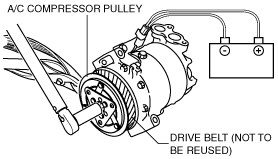
1. When removing or installing the bolt, hold the pressure plate in place as shown in the figure.
am3zzw00010993
|
2. When installing a new A/C compressor body, replace the recommended bolt.
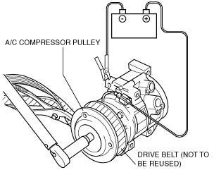
Bolt Removal/Installation Note (SKYACTIV-G 2.0, MZR 2.0, MZR 2.0 DISI i-stop, MZR 2.3 DISI Turbo, MZR 2.5)
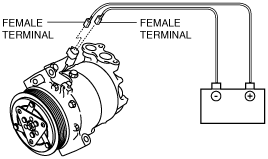
1. When removing or installing the bolt, lock the A/C compressor pulley against rotation using the following procedure
am3zzw00011945
|
am3zzw00010994
|
2. When installing a new A/C compressor body, replace the recommended bolt.
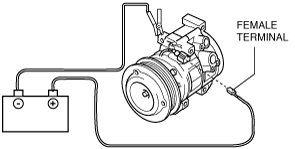
Nut Removal/Installation Note (MZ-CD 1.6)
1. When removing or installing the nut, lock the A/C compressor pulley against rotation using the following procedure
am3zzw00010995
|
am3zzw00010996
|
2. When installing a new A/C compressor body, replace the recommended nut.
Stator and Thermal Protector Removal Note
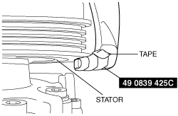
1. After removing the stator and thermal protector, completely remove the silicone adhering to the A/C compressor side.
Stator and Thermal Protector Installation Note
1. Apply approx. 1 g {0.04 oz} of silicone (Shin-Etsu Silicone KE-347W or similar) to the contact surface of the thermal protector, then thoroughly install it onto the A/C compressor, leaving no gaps.
am3zzw00010997
|
A/C Compressor Pulley Removal Note
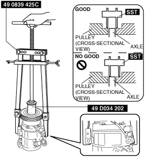
1. Remove the A/C compressor pulley using the SSTs (49 0839 425C, 49 SE01 160).
acxuuw00002994
|
am3zzw00010998
|
A/C Compressor Pulley Installation Note
1. Install the inner wheel of the pulley using SST (49 D034 202) to the compressor.
acxuuw00002995
|
Snap Ring Removal/Installation Note
1. Remove/install the snap ring using a snap ring pliers.
am3zzw00010999
|
Screw Installation Note
1. When installing a new stator, replace the screw.
O-ring Installation Note
1. When installing a new oil plug, replace the O-ring.
Clamp Installation Note
1. When installing a new stator and thermal protector, replace the clamp.
Shim Installation Note
1. First, insert the 1mm (0.039 in) thick shim into the shaft.
am3zzw00011000
|