 |
am3zzw00005110
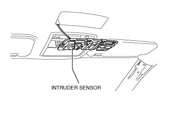
INTRUDER SENSOR INSPECTION
id091400517300
1. Remove the interior light. (See INTERIOR LIGHT REMOVAL/INSTALLATION.)
2. Remove the intruder sensor cover. (See INTRUDER SENSOR COVER REMOVAL/INSTALLATION.)
3. Measure the voltage according to the terminal voltage table.
am3zzw00005110
|
4. Disconnect the negative battery cable. (See BATTERY REMOVAL/INSTALLATION [MZR 1.5, MZR 1.6].) (See BATTERY REMOVAL/INSTALLATION [MZR 2.0, MZR 2.5].) (See BATTERY REMOVAL/INSTALLATION [MZR 2.0 DISI i-stop].) (See BATTERY REMOVAL/INSTALLATION [MZR 2.3 DISI Turbo].) (See BATTERY REMOVAL/INSTALLATION [MZ-CD 1.6].) (See BATTERY REMOVAL/INSTALLATION [MZR-CD 2.2].)
Terminal Voltage Table (Reference)
am2zzw00003487
|
|
Terminal |
Signal name |
Connected to |
Measurement condition |
Voltage (V) |
Inspection item(s) |
|---|---|---|---|---|---|
|
B
|
GND
|
Body ground
|
Under any condition
|
1.0 or less
|
Ground
|
|
C
|
DATA
|
BCM
|
Terminal used for communication therefore determination based on terminal voltage inspection not possible.
|
||
|
D
|
Power supply
|
BCM
|
Under any condition
|
B+
|
BCM
|