MANUAL AIR CONDITIONER SYSTEM [MANUAL AIR CONDITIONER]
id0740a2005000
Outline
• The climate control unit performs the following controls based on the signals from each switch/dial and the sensor.
|
Basic control
|
Control description
|
|
Airflow volume control
|
• Start-up burnt-out prevention function (7-speed type airflow volume control dial)
• Delay control (7-speed type airflow volume control dial)
• Generator output request function
|
|
Air intake control
|
• Defroster control
• REC mode control under severe heat
|
|
A/C compressor control
|
• A/C signal on/off control
• MAX A/C control (with MAX A/C control)
• A/C cut-off control
|
|
Supplementary function
|
|
Air conditioner i-stop control
|
|
Fail-safe function
|
Function
Airflow volume control (7-speed type airflow volume control dial)
-
• The climate control unit changes the blower motor applied voltage in seven steps according to the operation of the airflow volume control dial.
|
Airflow volume control dial
|
Blower motor applied voltage
|
|
1st
|
3.2 V
|
|
2nd
|
4.8 V
|
|
3rd
|
6.4 V
|
|
4th
|
7.9 V
|
|
5th
|
10.1 V
|
|
6th
|
11.2 V
|
|
7th
|
12.5 V
|
-
Start-up burn-out prevention function
-
• The start-up burn-out prevention function prevents the blower motor from being burnt out because of excess current.
• When the blower motor is started-up from the stopped status, the blower motor applied voltage is fixed at 3.1 V for 1 s.
-
Delay control
-
• The retard control retards the ignition voltage to the blower motor for approx. 1 s and operates the motor to prevent blower motor damage due to inrush current when the blower motor switch is switched.
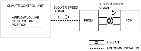
Generator output request function
-
• When the climate control unit detects a 4-speed or more setting on the airflow volume control dial (7-speed type airflow volume control dial)/3-speed or more setting on the airflow volume control dial (4-speed type airflow volume control dial), the climate control unit sends a blower speed signal to the PCM and outputs power from the generator to supplement battery power consumption using a high blower motor speed.
Air intake control
-
• The climate control unit switches the air intake mode based on the REC/FRESH switch operation.
|
Air intake mode
|
REC switch operation
|
|
FRESH
|
Fixed to FRESH when the FRESH switch is turned on during REC mode
|
|
REC
|
Fixed to REC when the RECIRCULATE switch is turned on during FRESH mode
|
-
Defroster control
-
• The defroster control improves the defrosting effect.
• When the defroster switch turns on, the climate control unit fixes the air intake mode to FRESH.
• The defroster correction fixes the air intake mode to FRESH when the airflow mode is DEFROSTER.
• The air intake is fixed at FRESH even if it has been set to REC manually.
-
REC mode control under severe heat
-
• When the vehicle is driven at a very low speed with the A/C on under a severe heat condition, the climate control unit may change the air intake mode from FRESH to REC automatically.
• Due to this, load to the A/C compressor is reduced.
• When the air intake mode is switched to REC, the indicator on the REC switch illuminates.
A/C compressor control
-
A/C signal on/off control
-
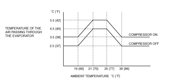
• When the A/C switch and fan switch are turned on, the climate control unit turns the A/C signal (magnetic clutch) on/off based on the temperature of the air passing through the evaporator.
• When the fan switch and A/C switch are turned on, the climate control unit controls the surface temperature of the evaporator so that it is within a certain range to prevent the evaporator from freezing.
• When the ambient temperature is low, the climate control unit sets the A/C signal (magnetic clutch) off-temperature to low to prevent window fogging.
-
MAX A/C control
-
• When the temperature control dial is set to the MAX COLD position, the climate control unit performs the MAX A/C control (when the airflow mode is VENT or BI-LEVEL).
• The MAX A/C control controls the air conditioner as follows:
-
― Sets the intake mode to REC.
― Turns on the A/C compressor.
-
A/C cut-off control
-
Air conditioner i-stop control
-
• The climate control unit determines i-stop control according to the operation condition of the air conditioner system and sends i-stop request signals to the PCM.
Fail-safe
-
• If a malfunction is detected by the malfunction detection function, the fail-safe function performs the following controls to prevent an operation malfunction of the air conditioner and malfunction of output devices.
Fail-safe function table
|
Part where malfunction is determined
|
Malfunction determined when ignition switched ON
|
Malfunction already exists when ignition switched ON
|
|
Ambient temperature sensor
|
Ambient temperature sensor input value is fixed at the value right before the malfunction.
|
Ambient temperature sensor input value is fixed at 15 °C {59 °F}.
|
|
Evaporator temperature sensor
|
A/C output OFF is controlled when the evaporator temperature sensor input value is at 0 °C {32 °F}.
|
←
|
|
Engine coolant temperature sensor
|
Engine coolant temperature sensor input value is fixed at 85 °C {185 °F}.
|
←
|
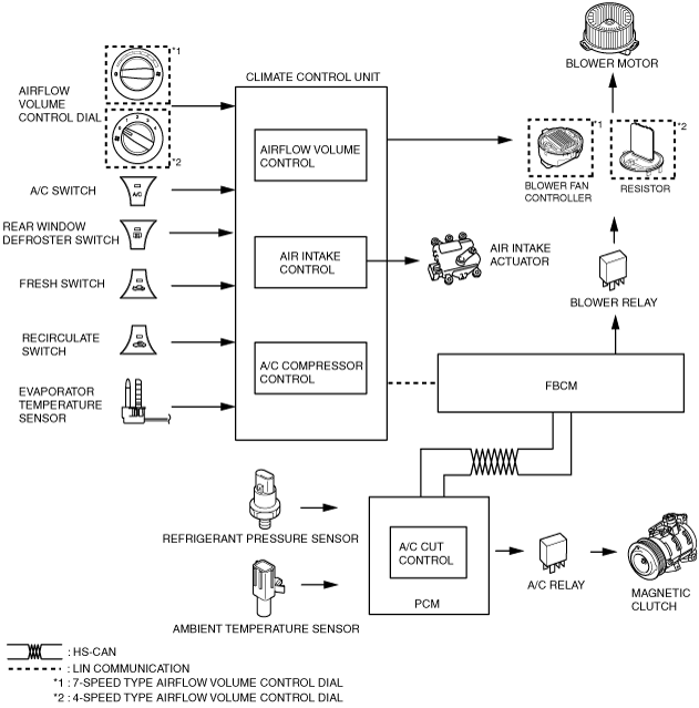
Construction
Block diagram
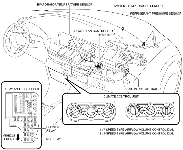
Structural view
Operation
Airflow volume control
-
• For the airflow volume control operation, refer to the blower system operation. (See
BLOWER SYSTEM.)
Generator output request function
-
7-speed type airflow volume control dial
-
1. When a 4-speed or more setting on the airflow volume control dial is detected, the climate control unit sends a blower speed signal to the PCM.
2. The PCM controls the generator voltage according to electrical load conditions based on the blower speed signal from the climate control unit.
-
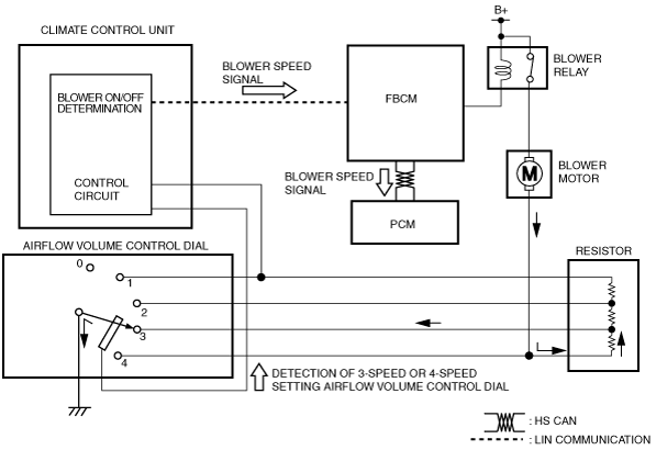
4-speed type airflow volume control dial
-
1. When a 3-speed or more setting on the airflow volume control dial is detected, the climate control unit sends a blower speed signal to the PCM.
2. The PCM controls the generator voltage according to electrical load conditions based on the blower speed signal from the climate control unit.
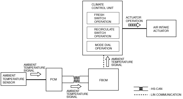
Air intake control
1. The climate control determines the air intake mode based on the operations of the FRESH switch, RECIRCULATE switch, mode dial and signals from each sensor which changes according to the vehicle environment.
2. The climate control unit drives the air intake actuator according to the result of the air intake mode determination and corrections.
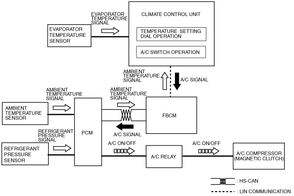
A/C compressor control
-
• The climate control unit sends the A/C signal to the PCM based on the signals sent from the A/C switch, airflow volume control dial, and evaporator temperature sensor.
• The PCM turns the A/C relay on/off based on the input signals from the A/C signal and A/C pressure sensor and controls the A/C compressor (magnetic clutch) operation.
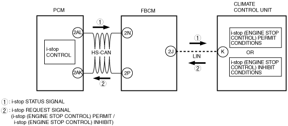
Air conditioner i-stop control
-
i-stop request control (i-stop (engine stop control) permit)
-
• The climate control unit sends i-stop (engine stop control) permit or inhibit request signals to the PCM according to the operation condition of the air conditioner system.
-
i-stop (engine stop control) inhibit request
-
• The climate control unit sends an i-stop (engine-stop control) permit signal to the PCM when it does not detect any of the following conditions:
i-stop (engine stop control) inhibit conditions
|
No.
|
Item
|
Vehicle condition
|
|
1
|
• Blower motor operation status
• Airflow mode
|
• Blower motor is ON
• Airflow mode during defrost
|
|
2
|
Airflow volume control dial status
|
Airflow volume control dial: 7th
|
|
3
|
Ambient temperature
|
Ambient temperature is -10 °C {14 °F} or below, or 50 °C {122 °F} or more
|
|
4
|
Engine coolant temperature
|
Engine coolant temperature does not meet the i-stop permit conditions (Comfortable cabin temperature control not performed)
|
|
5
|
Evaporator temperature
|
Evaporator temperature does not meet the i-stop permit conditions (Comfortable cabin temperature control not performed)
|