 |
am3uuw00010466
FRONT MAP LIGHT INSPECTION
id091800808600
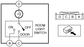
Single Light Type
1. Perform the following procedure.
2. Remove the front map light. (See FRONT MAP LIGHT REMOVAL/INSTALLATION.)
3. Verify that the continuity between the front map light terminals is as indicated in the table.
am3uuw00010466
|
am3uuw00010467
|
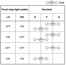
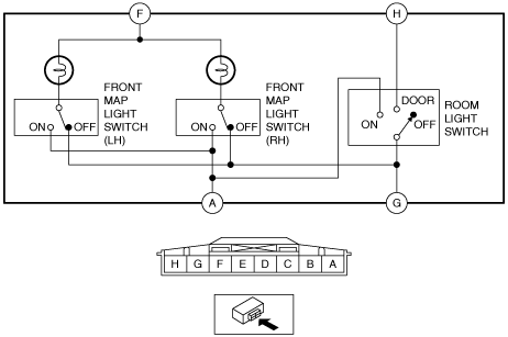
Dual Light Type
Front map light switch
1. Disconnect the negative battery cable. (See NEGATIVE BATTERY CABLE DISCONNECTION/CONNECTION [MZR 1.6].) (See NEGATIVE BATTERY CABLE DISCONNECTION/CONNECTION [SKYACTIV-G 1.5, SKYACTIV-G 2.0, SKYACTIV-G 2.5].) (See NEGATIVE BATTERY CABLE DISCONNECTION/CONNECTION [SKYACTIV-D 2.2].)(See NEGATIVE BATTERY CABLE DISCONNECTION/CONNECTION [SKYACTIV-D 1.5].)
2. Remove the front map light. (See FRONT MAP LIGHT REMOVAL/INSTALLATION.)
3. Verify that the continuity between the front map light terminals is as indicated in the table.
am3uuw00010468
|
am3uuw00010469
|
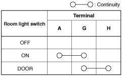
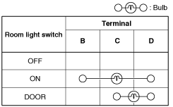
Room light switch
1. Disconnect the negative battery cable. (See NEGATIVE BATTERY CABLE DISCONNECTION/CONNECTION [MZR 1.6].) (See NEGATIVE BATTERY CABLE DISCONNECTION/CONNECTION [SKYACTIV-G 1.5, SKYACTIV-G 2.0, SKYACTIV-G 2.5].) (See NEGATIVE BATTERY CABLE DISCONNECTION/CONNECTION [SKYACTIV-D 2.2].)(See NEGATIVE BATTERY CABLE DISCONNECTION/CONNECTION [SKYACTIV-D 1.5].)
2. Remove the front map light. (See FRONT MAP LIGHT REMOVAL/INSTALLATION.)
3. Verify that the continuity between the front map light terminals is as indicated in the table.
am3uuw00010470
|
am3uuw00010469
|