THROTTLE POSITION (TP) SENSOR INSPECTION [ZY, Z6]
id0140a0802700
-
Note
-
• Before performing the following inspection, make sure to follow the procedure as indicated in the troubleshooting flowchart. (See
HOW TO USE THIS MANUAL.)
Resistance Inspection
1. Verify the following.
-
• Throttle valve closed status
2. Disconnect the TP sensor connector.
3. Verify that the resistance between terminals B and C changes moderately corresponding to the throttle valve openings.
-
• If the resistance change is verified, go to the next step.
4. Measure the resistance between terminals A and B.
-
• If the monitor item condition/specification (reference) is not within the specification, even though there is no malfunction, perform the “Circuit Open/Short Inspection”.
-
TP sensor resistance
-
2.5—6.0 kilohms [25 °C {77 °F}]
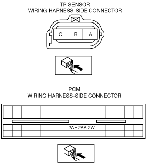
Circuit Open/Short Inspection
1. Remove the PCM connector cover.
2. Disconnect the PCM connector. (See INTAKE-AIR SYSTEM REMOVAL/INSTALLATION [ZY, Z6].)
3. Inspect the following wiring harness for open or short circuit (continuity check).
Open circuit
-
• If there is no continuity, there is an open circuit. Repair or replace the wiring harness.
-
― TP sensor terminal A and PCM terminal 2W
― TP sensor terminal B and PCM terminal 2AE
― TP sensor terminal C and PCM terminal 2AA
Short circuit
-
• If there is continuity, there is a short circuit. Repair or replace the wiring harness.
-
― TP sensor terminal A and body GND
― TP sensor terminal B and power supply
― TP sensor terminal C and power supply
― TP sensor terminal C and body GND