NEUTRAL SWITCH INSPECTION [LF, L3]
id0140a6800800
-
Note
-
• Before performing the following inspection, make sure to follow the procedure as indicated in the troubleshooting flowchart.
Continuity Inspection
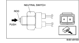
1. Remove the neutral switch. (See NEUTRAL SWITCH REMOVAL/INSTALLATION [G35M-R].)
2. Verify that the continuity between neutral switch terminals A and B is as indicated in the table.
-
• If it can be verified, perform the "Circuit Open/Short Inspection".
-
• If it cannot be verified, replace the neutral switch.
|
Measured condition
|
Continuity
|
|
Rod pushed
|
Continuity detected
|
|
Except above
|
No continuity
|
Circuit Open/Short Inspection
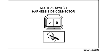
1. Disconnect the PCM connector. (See PCM REMOVAL/INSTALLATION [LF, L3].)
2. Inspect the following harness for open or short. (Continuity check)
Open circuit
-
• Neutral switch terminal A and PCM terminal 1S
-
• Neutral switch terminal B and body GND
Short circuit
-
• Neutral switch terminal B and body GND