|
am3zzw00013145
PCM INSPECTION [LF, L3]
id0140a6802500
Without Using the SST
am3zzw00013145
|
|
Terminal |
Signal |
Connected to |
Test condition |
Voltage (V) |
Inspection item |
|
|---|---|---|---|---|---|---|
|
1A*1
|
VSS power supply
|
VSS
|
Ignition switch is turned to the ON position.
|
B+
|
• Related wiring harness
|
|
|
1B*1
|
Shift solenoid A
|
Shift solenoid A
|
• Shift solenoid A
• Related wiring harness
|
|||
|
1C*1
|
Shift solenoid B
|
Shift solenoid B
|
• Shift solenoid B
• Related wiring harness
|
|||
|
1D*1
|
Shift solenoid C
|
Shift solenoid C
|
• Shift solenoid C
• Related wiring harness
|
|||
|
1E*1
|
Shift solenoid D
|
Shift solenoid D
|
P or N position
|
B+
|
• Shift solenoid D
• Related wiring harness
|
|
|
Except above
|
1.0 or less
|
|||||
|
1F*1
|
Shift solenoid E
|
Shift solenoid E
|
During TCC operation
|
B+
|
• Shift solenoid E
• Related wiring harness
|
|
|
Except above
|
1.0 or less
|
|||||
|
1G*1
|
Pressure control solenoid (+)
|
Pressure control solenoid
|
• Pressure control solenoid
• Related wiring harness
|
|||
|
1H*1
|
Pressure control solenoid (–)
|
Pressure control solenoid
|
• Pressure control solenoid
• Related wiring harness
|
|||
|
1I
|
—
|
—
|
—
|
—
|
—
|
|
|
1J*1
|
Vehicle speed
|
VSS
|
• VSS
• Related wiring harness
|
|||
|
1K*1
|
Manual up
|
Up switch
|
Ignition switch is turned to the ON position.
|
Detects up-shift operation of selector lever in M range
|
1.0 or less
|
• Selector lever
• Related wiring harness
|
|
Others
|
B+
|
|||||
|
1L*5
|
Oil pressure switch
|
Oil pressure switch
|
Oil pressure switch OFF
|
B+
|
• Oil pressure switch
• Related wiring harnesses
|
|
|
Oil pressure switch ON
|
1.0 or less
|
|||||
|
1M*1
|
Input/turbine speed sensor (+)
|
Input/turbine speed sensor
|
• Input/turbine speed sensor
• Related wiring harness
|
|||
|
1N
|
—
|
—
|
—
|
—
|
—
|
|
|
1O
|
*2Clutch operation
|
CPP switch
|
Clutch pedal depressed
|
Below 1.0
|
• CPP
• Related harness
|
|
|
Clutch pedal released
|
B+
|
|||||
|
*1M range switch
|
M range switch
|
Ignition switch is turned to the ON position.
|
M range
|
1.0 or less
|
• Selector lever
• Related wiring harness
|
|
|
Except above
|
B+
|
|||||
|
1P*1
|
Manual down
|
Down switch
|
Ignition switch is turned to the ON position.
|
Detects down-shift operation of selector lever in M range
|
1.0 or less
|
• Selector lever
• Related wiring harness
|
|
Others
|
B+
|
|||||
|
1Q*1
|
Input/turbine speed sensor (–)
|
Input/turbine speed sensor
|
• Input/turbine speed sensor
• Related wiring harness
|
|||
|
1R
|
Refrigerant pressure switch (middle)
|
Refrigerant pressure switch (middle)
|
A/C ON
|
Refrigerant pressure is above 1.52 MPa {15.5 kgf/cm2, 220 psi}
|
Below 1.0
|
• Refrigerant pressure switch
• Related harness
|
|
Refrigerant pressure is below 1.23 MPa {12.5 kgf/cm2, 178 psi}
|
B+
|
|||||
|
1S
|
*2Neutral position
|
Neutral switch
|
Shift lever is at neutral position
|
Below 1.0
|
• Neutral switch
• Related harness
|
|
|
Shift lever is not at neutral position
|
B+
|
|||||
|
*1Selector lever position
|
TR switch
|
Ignition switch is turned to the ON position.
|
P position
|
Approx. 4.6
|
• TR switch
• Related wiring harness
|
|
|
R position
|
Approx. 3.9
|
|||||
|
N position
|
Approx. 3.2
|
|||||
|
D range
|
Approx. 2.5
|
|||||
|
M range
|
Approx. 2.5
|
|||||
|
1T
|
—
|
—
|
—
|
—
|
—
|
|
|
1U*1
|
ATF temperature
|
TFT sensor
|
Ignition switch is turned to the ON position.
|
TFT is 20 °C {68 °F}
|
Approx. 3.3
|
• TFT sensor
• Related wiring harness
|
|
TFT is 40 °C {104 °F}
|
Approx. 2.4
|
|||||
|
TFT is 60 °C {140 °F}
|
Approx. 1.5
|
|||||
|
1V
|
—
|
—
|
—
|
—
|
—
|
|
|
1W
|
Cooling fan control
|
Fan control module
|
• Inspect using the wave profile.
|
• Fan control module.
• Related harness
|
||
|
1X
|
—
|
—
|
—
|
—
|
—
|
|
|
1Y
|
—
|
—
|
—
|
—
|
—
|
|
|
1Z
|
—
|
—
|
—
|
—
|
—
|
|
|
1AA
|
Sensor GND
|
MAF/IAT sensor, BARO sensor, TFT sensor*1, TR switch*1
|
Under any condition
|
Below 1.0
|
• Related harness
|
|
|
1AB*3
|
Starter relay control
|
Starter relay
|
Under any condition
|
Below 1.0
|
• Starter relay
• Related harness
|
|
|
1AC
|
MAF
|
MAF sensor
|
Ignition switch ON
|
Approx. 0.7
|
• MAF sensor
• Related harness
|
|
|
Idle (after warm up)
|
Approx. 1.2
|
|||||
|
1AD
|
—
|
—
|
—
|
—
|
—
|
|
|
1AE
|
Constant voltage (Vref)
|
MAP sensor
|
Ignition switch ON
|
Approx. 5.0
|
• Related harness
|
|
|
1AF
|
—
|
—
|
—
|
—
|
—
|
|
|
1AG
|
Atmospheric pressure
|
BARO sensor
|
Ignition switch ON (at sea level)
|
Approx. 4.0
|
• BARO sensor
• Related harness
|
|
|
1AH
|
IAT
|
MAF/IAT sensor
|
Ignition switch ON
|
IAT 0 °C
{32 °F}
|
Approx.
3.43
|
• IAT sensor
• Related harness
|
|
IAT 20 °C
{68 °F}
|
Approx.
2.38
|
|||||
|
IAT 40 °C
{104 °F}
|
Approx.
1.49
|
|||||
|
IAT 60 °C
{140 °F}
|
Approx.
0.89
|
|||||
|
IAT 80 °C
{176 °F}
|
Approx.
0.53
|
|||||
|
IAT 100 °C
{212 °F}
|
Approx.
0.33
|
|||||
|
1AI
|
CAN (L)
|
Instrument cluster, ABS HU/CM,
DSC HU/CM,
Electrical P/S pump
|
Because this terminal is for CAN, good/no good judgment by terminal voltage is not possible.
|
• Related harness
|
||
|
1AJ
|
—
|
—
|
—
|
—
|
—
|
|
|
1AK
|
—
|
—
|
—
|
—
|
—
|
|
|
1AL
|
—
|
—
|
—
|
—
|
—
|
|
|
1AM
|
CAN (H)
|
Instrument cluster, ABS HU/CM,
DSC HU/CM,
Electrical P/S pump
|
Because this terminal is for CAN, good/no good judgment by terminal voltage is not possible.
|
• Related harness
|
||
|
1AN
|
A/C
|
A/C relay
|
Idle
|
A/C operating
|
Below 1.0
|
• A/C relay
• Related harness
|
|
A/C not operating
|
B+
|
|||||
|
1AO
|
—
|
—
|
—
|
—
|
—
|
|
|
1AP
|
A/C on signal
|
Refrigerant pressure switch (high and low)
|
Idle
|
A/C switch and fan switch on
|
Below 1.0
|
• Refrigerant pressure switch
• Related harness
|
|
A/C switch off
|
B+
|
|||||
|
1AQ*4
|
Fuel pump control
|
Fuel pump relay
|
Ignition switch ON
|
B+
|
• Fuel pump relay
• Related harness
|
|
|
Cranking
|
Below 1.0
|
|||||
|
Idle
|
Below 1.0
|
|||||
|
1AR*3
|
Fuel pump control
|
Fuel pump relay
|
Ignition switch ON
|
B+
|
• Fuel pump relay
• Related harness
|
|
|
Cranking
|
Below 1.0
|
|||||
|
Idle
|
Below 1.0
|
|||||
|
1AS
|
—
|
—
|
—
|
—
|
—
|
|
|
1AT
|
Main relay control
|
Main relay
|
Ignition switch OFF
|
Below 1.0
|
• Main relay
• Related harness
|
|
|
Ignition switch ON
|
||||||
|
1AU
|
Brake
|
Brake switch
|
Brake pedal depressed
|
B+
|
• Brake switch
• Related harness
|
|
|
Brake pedal released
|
Below 1.0
|
|||||
|
1AV*1
|
Internal GND
|
Input/turbine speed sensor shield wire
|
Under any condition
|
1.0 or less
|
• Related wiring harness
|
|
|
1AW
|
—
|
—
|
—
|
—
|
—
|
|
|
1AX
|
—
|
—
|
—
|
—
|
—
|
|
|
1AY
|
—
|
—
|
—
|
—
|
—
|
|
|
1AZ
|
GND
|
GND
|
Under any condition
|
Below 1.0
|
• Related harness
|
|
|
1BA
|
Back-up power supply
|
Battery (positive terminal)
|
Under any condition
|
B+
|
• Battery
• Related harness
|
|
|
1BB
|
—
|
—
|
—
|
—
|
—
|
|
|
1BC
|
GND
|
GND
|
Under any condition
|
Below 1.0
|
• Related harness
|
|
|
1BD
|
GND
|
GND
|
Under any condition
|
Below 1.0
|
• Related harness
|
|
|
1BE
|
B+
|
Main relay
|
Ignition switch OFF
|
Below 1.0
|
• Battery
• Related harness
|
|
|
Ignition switch ON
|
B+
|
|||||
|
1BF
|
—
|
—
|
—
|
—
|
—
|
|
|
1BG
|
GND
|
GND
|
Under any condition
|
Below 1.0
|
• Related harness
|
|
|
1BH
|
GND
|
GND
|
Under any condition
|
Below 1.0
|
• Related harness
|
|
|
2A
|
—
|
—
|
—
|
—
|
—
|
|
|
2B
|
—
|
—
|
—
|
—
|
—
|
|
|
2C
|
Rear HO2S heater control
|
HO2S (Rear) heater
|
Ignition switch ON
|
Engine speed below 3,900 rpm
|
B+
|
• HO2S (Front) heater.
• Related harness
|
|
Engine speed above 3,900 rpm
|
Below 1.0
|
|||||
|
2D
|
—
|
—
|
—
|
—
|
—
|
|
|
2E
|
IAC (+)
|
IAC valve
|
• Inspect using the wave profile.
|
• IAC valve
• Related harness
|
||
|
2F
|
IAC (–)
|
IAC valve
|
• Inspect using the wave profile.
|
• IAC valve
• Related harness
|
||
|
2G
|
Front HO2S heater control
|
HO2S (Front) heater
|
• Inspect using the wave profile.
|
• HO2S (Front) heater.
• Related harness
|
||
|
2H
|
—
|
—
|
—
|
—
|
—
|
|
|
2I
|
Throttle position
|
TP sensor
|
Ignition switch ON
|
CTP
|
0.65—1.15
|
• TP sensor
• Related harness
|
|
WOT
|
4.3—4.8
|
|||||
|
2J
|
—
|
—
|
—
|
—
|
—
|
|
|
2K
|
—
|
—
|
—
|
—
|
—
|
|
|
2L
|
—
|
—
|
—
|
—
|
—
|
|
|
2M
|
—
|
—
|
—
|
—
|
—
|
|
|
2N
|
—
|
—
|
—
|
—
|
—
|
|
|
2O
|
—
|
—
|
—
|
—
|
—
|
|
|
2P
|
GND
|
GND
|
Under any condition
|
Below 1.0
|
• Related harness
|
|
|
2Q
|
Knocking (+)
|
KS
|
Ignition switch ON (Use digital type voltmeter, because measurement voltage will be detected less than true voltage when using analog type voltmeter)
|
Approx. 4.3
|
• KS
• Related harness
|
|
|
2R
|
Knocking (–)
|
KS
|
Ignition switch ON (Use digital type voltmeter, because measurement voltage will be detected less than true voltage when using analog type voltmeter)
|
Below 1.0
|
• KS
• Related harness
|
|
|
2S
|
—
|
—
|
—
|
—
|
—
|
|
|
2T
|
—
|
—
|
—
|
—
|
—
|
|
|
2U
|
CMP (+)
|
CMP sensor
|
• Inspect using the wave profile.
|
• CMP sensor
• Related harness
|
||
|
2V
|
CMP (–)
|
CMP sensor
|
• Inspect using the wave profile.
|
• CMP sensor
• Related harness
|
||
|
2W
|
Constant voltage (Vref)
|
BARO sensor,
TP sensor
|
Ignition switch ON
|
Approx. 5.0
|
• Related harness
|
|
|
2X
|
—
|
—
|
—
|
—
|
—
|
|
|
2Y
|
CKP (+)
|
CKP sensor
|
• Inspect using the wave profile.
|
• CKP sensor
• Related harness
|
||
|
2Z
|
CKP (–)
|
CKP sensor
|
• Inspect using the wave profile.
|
• CKP sensor
• Related harness
|
||
|
2AA
|
Sensor GND
|
HO2S (Front, Rear),
ECT sensor,
TP sensor,
MAP sensor
|
Under any condition
|
Below 1.0
|
• Related harness
|
|
|
2AB
|
—
|
—
|
—
|
—
|
—
|
|
|
2AC
|
—
|
—
|
—
|
—
|
—
|
|
|
2AD
|
—
|
—
|
—
|
—
|
—
|
|
|
2AE
|
—
|
—
|
—
|
—
|
—
|
|
|
2AF*5
|
OCV control
|
OCV
|
• Inspect using the wave profile.
|
• OCV valve
• Related wiring harness
|
||
|
2AG
|
Front HO2S
|
HO2S (front)
|
• Inspect using the wave profile.
|
• HO2S (front)
• Related harness
|
||
|
2AH
|
Rear HO2S
|
HO2S (rear)
|
Ignition switch ON
|
Approx. 0
|
• HO2S (rear)
• Related harness
|
|
|
Idle (after warm up)
|
Alternates between 0 and 1.0
|
|||||
|
2AI
|
Variable tumble control
|
Variable tumble solenoid valve
|
ECT above 63 °C {145 °F} while idling.
|
B+
|
• Variable tumble solenoid valve
• Related harness
|
|
|
ECT below 63 °C {145 °F} and engine speed below 3,750 rpm
|
Below 1.0
|
|||||
|
2AJ
|
Variable intake-air control
|
Variable intake-air solenoid valve
|
Ignition switch ON
|
Below 1.0
|
• Variable intake-air solenoid valve
• Related harness
|
|
|
Engine speed: below 4,750 rpm (LF), 4,600 rpm (L3)
|
Below 1.0
|
|||||
|
Engine speed: above 4,750 rpm (LF), 4,600 rpm (L3)
|
B+
|
|||||
|
2AK
|
ECT
|
ECT sensor
|
Ignition switch ON
|
IAT 20 °C
{68 °F}
|
3.04—3.14
|
• ECT sensor
• Related harness
|
|
IAT 40 °C
{104 °F}
|
2.09—2.21
|
|||||
|
IAT 60 °C
{140 °F}
|
1.29—1.39
|
|||||
|
IAT 80 °C
{176 °F}
|
0.76—0.83
|
|||||
|
IAT 100 °C
{212 °F}
|
0.45—0.49
|
|||||
|
2AL
|
Manifold absolute pressure
|
MAP sensor
|
Ignition switch ON (at sea level)
|
Approx. 4.1
|
• MAP sensor
• Related harness
|
|
|
Idle
|
Approx. 1.2
|
|||||
|
2AM
|
Generator output voltage
|
Generator
(terminal P)
|
• Inspect using the wave profile.
|
• Generator
• Related harness
|
||
|
2AN
|
Purge control
|
Purge solenoid valve
|
• Inspect using the wave profile.
|
• Purge solenoid valve
• Related harness
|
||
|
2AO
|
—
|
—
|
—
|
—
|
—
|
|
|
2AP
|
—
|
—
|
—
|
—
|
—
|
|
|
2AQ
|
Generator field coil control
|
Generator
(terminal D)
|
• Inspect using the wave profile.
|
• Following PIDs: IAT, ECT, RPM, VPWR, ALTT V.
• Generator
• Related harness
|
||
|
2AR
|
EGR valve #2 coil control
|
EGR valve
(terminal A)
|
Ignition switch ON
|
B+
|
• EGR valve
• Related harness
|
|
|
Idle
|
B+
|
|||||
|
2AS
|
—
|
—
|
—
|
—
|
—
|
|
|
2AT
|
—
|
—
|
—
|
—
|
—
|
|
|
2AU
|
EGR valve #1 coil control
|
EGR valve
(terminal E)
|
Ignition switch ON
|
Below 1.0
|
• EGR valve
• Related harness
|
|
|
Idle
|
Below 1.0
|
|||||
|
2AV
|
EGR valve #4 coil control
|
EGR valve
(terminal F)
|
Ignition switch ON
|
Below 1.0
|
• EGR valve
• Related harness
|
|
|
Idle
|
Below 1.0
|
|||||
|
2AW
|
—
|
—
|
—
|
—
|
—
|
|
|
2AX
|
—
|
—
|
—
|
—
|
—
|
|
|
2AY
|
EGR valve #3 coil control
|
EGR valve (terminal B)
|
Ignition switch ON
|
B+
|
• EGR valve
• Related harness
|
|
|
Idle
|
B+
|
|||||
|
2AZ
|
Fuel injection (#4)
|
Fuel injector No.4
|
• Inspect using the wave profile.
|
• Fuel injector No.4
• Related harness
|
||
|
2BA
|
—
|
—
|
—
|
—
|
—
|
|
|
2BB
|
Fuel injection (#1)
|
Fuel injector No.1
|
• Inspect using the wave profile.
|
• Fuel injector No.1
• Related harness
|
||
|
2BC
|
Fuel injection (#2)
|
Fuel injector No.2
|
• Inspect using the wave profile.
|
• Fuel injector No.2
• Related harness
|
||
|
2BD
|
Fuel injection (#3)
|
Fuel injector No.3
|
• Inspect using the wave profile.
|
• Fuel injector No.3
• Related harness
|
||
|
2BE
|
IGT1
|
Ignition coil (No.1 cylinders)
|
• Inspect using the wave profile.
|
• Ignition coil
• Related harness
|
||
|
2BF
|
IGT2
|
Ignition coil (No.2 cylinders)
|
• Inspect using the wave profile.
|
• Ignition coil
• Related harness
|
||
|
2BG
|
IGT3
|
Ignition coil (No.3 cylinders)
|
• Inspect using the wave profile.
|
• Ignition coil
• Related harness
|
||
|
2BH
|
IGT4
|
Ignition coil (No.4 cylinders)
|
• Inspect using the wave profile.
|
• Ignition coil
• Related harness
|
||
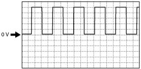
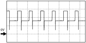
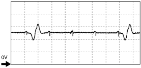
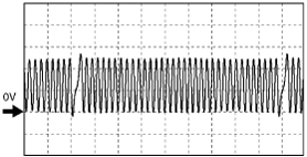
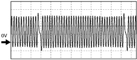
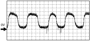
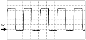
Inspection Using An Oscilloscope (Reference)
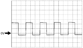
Shift solenoid A signal
am3zzw00013140
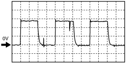
|
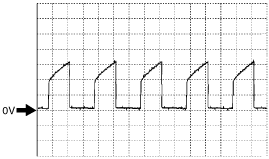
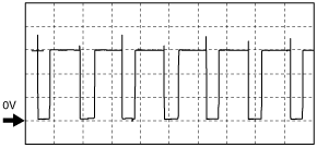
Shift solenoid B signal
am3zzw00013141
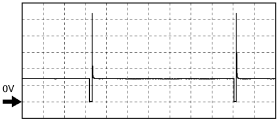
|
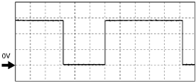
Shift solenoid C signal
am3zzw00013142
|
Pressure control solenoid (+) signal
am3zzw00013146
|
Pressure control solenoid (–) signal
am3zzw00013147
|
Vehicle speed signal
am3zzw00013148
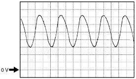
|
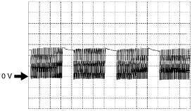
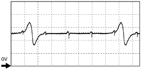
Input/turbine speed sensor (+) signal
am3zzw00013143
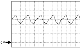
|
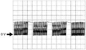
Input/turbine speed sensor (–) signal
am3zzw00013144
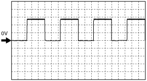
|
Cooling fan control signals
am3zzw00013149
|
IAC signal
(+)
am3zzw00013150
|
(–)
am3zzw00013151
|
HO2S (front) heater control signal
am3zzw00013152
|
CMP sensor signal
(+)
am3zzw00013153
|
(–)
am3zzw00013154
|
CKP sensor signal
(+)
am3zzw00013155
|
(–)
am3zzw00013156
|
HO2S (front) signal
am3zzw00013157
|
Generator output voltage signal
am3zzw00013158
|
Generator field coil control signal
am3zzw00013159
|
Fuel injection control
am3zzw00013160
|
IGT1, IGT2 control signals
am3zzw00013161
|
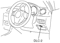
Using SST (WDS or Equivalent)
1. Connect the SST (WDS or equivalent) to the DLC-2.
am3zzw00013162
|
2. Turn the ignition switch to ON position.
3. Measure the PID value.
PID/DATA monitor table (reference)
|
Monitor item (Definition) |
Unit/Condition |
Condition/Specification (Reference) |
Inspection item |
PCM terminal |
|
|---|---|---|---|---|---|
|
AC_REQ
(Refrigerant pressure switch (low pressure switch, high pressure switch))
|
On/Off
|
• Refrigerant pressure is more than the specification or less than the specification. (Refrigerant pressure switch (low pressure switch, high pressure switch) is off.): Off
• Others: On
|
• Refrigerant pressure switch (low pressure switch, high pressure switch)
|
1AP
|
|
|
ACCS
(A/C relay)
|
On/Off
|
• Ignition switch ON: Off
• A/C switch ON and fan switch ON at idle: On
|
The following PIDs: RPM, TP, ECT, ACSW.
A/C relay
|
1AN
|
|
|
ALTF
(Generator field coil control duty value)
|
%
|
• Ignition switch ON: 0%
• Idle: 0—100%
• Just after A/C switch ON and fan switch ON at idle: Duty value rises
|
The following PIDs: IAT, ECT, RPM, VPWR, ALTT V.
Generator
|
2AQ
|
|
|
ALTT V
(Generator output voltage)
|
V
|
• Ignition switch ON: 0 V
• Idle: Approx. 14 V*1 (E/L not operating)
|
Generator
|
2AM
|
|
|
ARPMDES
(Target engine speed)
|
RPM
|
• Indicate the target engine speed
|
The following PIDs: CPP, CPP/PNP, PSP, ECT, IAT, RPM, TP, MAF, BARO, VSS, AC_REQ, COLP
IAC valve
|
—
|
|
|
BARO
(Barometric pressure)
|
KPa
|
• ignition switch ON: indicate the atmospheric pressure
|
BARO sensor
|
1AG
|
|
|
V
|
• Approx. 4 V (at sea level)
|
||||
|
BOO
(Brake switch)
|
On/Off
|
• Brake pedal depressed: On
• Brake pedal released: Off
|
Brake switch
|
1AU
|
|
|
CATT11_DSD
(Catalyst temperature)
|
°C
|
°F
|
• Indicate the catalyst temperature
|
—
|
—
|
|
CHRGLP
(Generator warning light)
|
On/Off
|
• Ignition switch ON: On
• Idle: Off
|
Perform applicable DTC troubleshooting.
|
—
|
|
|
COLP
(Refrigerant pressure switch (middle))
|
On/Off
|
• Refrigerant pressure switch (middle) ON*4 at idle: On
• Refrigerant pressure switch (middle) OFF*5 at idle: Off
|
Refrigerant pressure switch
|
1R
|
|
|
CPP
(Clutch pedal position)
|
On/Off
|
• Clutch pedal depressed: On
• Clutch pedal released: Off
|
CPP switch
|
1O
|
|
|
CPP/PNP
(Shift lever position)
|
Drive/Neutral
|
• Neutral position: Neutral
• Others: Drive
|
Neutral switch
|
1S
|
|
|
DTCCNT
(Number of DTC detected)
|
—
|
—
|
Perform applicable DTC troubleshooting
|
—
|
|
|
DWN SW*6
|
|||||
|
ECT
(Engine coolant temperature)
|
°C
|
°F
|
• Ignition switch ON: indicate the ECT
|
ECT sensor
|
2AK
|
|
V
|
• ECT 20 °C {68 °F}: 3.04—3.14 V
• ECT 60 °C {140 °F}: 1.29—1.39 V
|
||||
|
EQ_RAT_DSD
(Theoretical air/fuel ratio coefficient to calculate target air/fuel ratio)
|
—
|
• Idle: approx. 1
• Racing (after warm up): 0.8—1
|
The following PIDs: IAT, RPM, ECT, MAF, O2S11,BARO, INGEAR, VPWR.
|
—
|
|
|
EVAPCP
(Purge solenoid valve duty value)
|
%
|
• Ignition switch ON: 0%
• Idle: 0—9%
|
The following PIDs: IAT, RPM, ECT, MAF, O2S11,BARO, INGEAR, VPWR.
|
2AN
|
|
|
FAN_DUTY
(Cooling fan control)
|
%
|
• When all of following condition are met: 90%
|
The following PIDs: RPM, TP, ECT, ACSW, COLP, TEST.
Fan control module
|
1W
|
|
|
FP
(Fuel pump relay)
|
On/Off
|
• Ignition switch ON: On (1 s) →Off
• Idle: ON
• Cranking: On
|
The following PIDs: RPM.
Fuel pump relay
|
1AR*8
1AQ*9
|
|
|
FUELPW
(Fuel injector duration)
|
ms
|
• Ignition switch ON: 0 ms
• Idle (after warm up): approx. 2.0 ms
|
The following PIDs: IAT, MAF, TP, MAP, ECT, RPM, O2S11, O2S12, INGEAR, ACSW, VPWR, ALTT V.
Fuel injector
|
2AZ
2BB
2BC
2BD
|
|
|
FUELSYS
(Fuel system status)
|
OL/OL_Fault/CL_Fault/CL/OL_Drive
|
• Ignition switch ON: OL-Drive (Open loop)
• Idle (after warm up): CL (Closed loop)
|
The following PIDs: IAT, MAF, TP, MAP, ECT, RPM, O2S11, O2S12, INGEAR, ACSW, VPWR, ALTT V.
Fuel injector
|
—
|
|
|
GEAR*6
|
|||||
|
GENVDSD
(Generator voltage desired)
|
V
|
• Indicate the generator voltage desired
|
Perform applicable DTC troubleshooting.
|
—
|
|
|
HTR11
(HO2S heater (front))
|
On/Off
|
• Idle (after warm up): OnÛOff
|
The following PIDs: IAT, MAF, TP, ECT, RPM, ACSW.
|
2G
|
|
|
HTR12
(HO2S heater (rear))
|
On/Off
|
• Ignition switch ON: Off (HO2S heater not operating)
• Idle: On (HO2S heater operating)
|
The following PIDs: IAT, MAF, ECT, RPM, ACSW.
|
2C
|
|
|
IAC
(IAC valve)
|
%
|
• Ignition switch ON: 0 %
• Idle: Approx. 20% (ECT 100 °C {212 °F} and E/L not operating)
|
The following PIDs: IAT, RPM, MAP, ECT, MAF, TP, INGEAR, ACSW.
IAC valve
|
2E
2F
|
|
|
IAT
(Intake air temperature)
|
°C
|
°F
|
• Ignition switch ON: indicate the IAT
|
IAT sensor
|
1AH
|
|
V
|
• IAT 20 °C {68 °F}: 2.4—2.6 V
• IAT 30 °C {86 °F}: 1.7—1.9 V
|
||||
|
IMRC
(Variable tumble solenoid valve)
|
On/Off
|
• Engine speed is below approx. 3,750 rpm and low ECT: On
• Others: Off
|
The following PIDs: TP, ECT, RPM.
Variable tumble solenoid valve
|
2AI
|
|
|
IMTV
(Variable Intake-air solenoid valve)
|
On/Off
|
• Engine speed is below approx. 4,750 rpm (LF), 4,600 rpm (L3): On
• Others: Off
|
The following PIDs: RPM.
Variable intake-air solenoid valve
|
2AJ
|
|
|
INGEAR
(Load/no load condition)
|
On/Off
|
MTX
• CPP or CPP/PNP is ON: Off
• Others: On
|
Perform applicable DTC troubleshooting.
|
1O
1S
|
|
|
ATX
• Driving range: On
• Except above: Off
|
• TR switch
|
—
|
|||
|
IVS
(CTP condition)
|
Idle/Off Idle
|
• CTP: Idle
• Others: Off Idle
|
Perform applicable DTC troubleshooting.
|
—
|
|
|
KNOCKR
(Knocking retard)
|
°
|
• Ignition switch ON: 0 °
• Idle: 0 °
|
KS
|
2Q
2R
|
|
|
LINEDES*6
|
|||||
|
LOAD
(Engine load)
|
%
|
• Ignition switch ON: 0%
• Idle (after warm up): approx.20%
|
MAF sensor
|
—
|
|
|
LONGFT1
(long term fuel trim)
|
%
|
• Idle (after warm up): –15—20%
|
Perform applicable DTC troubleshooting.
|
—
|
|
|
LPS*6
|
|||||
|
MAF
(Mass airflow)
|
g/s
|
• Ignition switch ON: approx. 0 g/s
• Idle (after warm up): approx. 2.5 g/s
|
MAF sensor
|
1AC
|
|
|
V
|
• Ignition switch ON: approx. 0.7 V
• Idle (after warm up): approx. 1.2 V
|
||||
|
MAP
(Manifold absolute pressure)
|
KPa
|
• Ignition switch ON (at sea level): approx. 101 kPa
• Idle: approx. 30 kPa
|
MAP sensor
|
2AL
|
|
|
V
|
• Ignition switch ON (at sea level): approx. 4.1 V
• Idle: approx. 1.2 V
|
||||
|
MIL
(Malfunction indicator lamp)
|
On/Off
|
• DTC stored: On
• DTC not stored: Off
|
Perform applicable DTC troubleshooting.
|
—
|
|
|
MIL_DIS
(Travelled distance since MIL illuminated)
|
km
|
mile
|
Indicate the travelled distance since the MIL illuminated
|
||
|
MNL SW*6
|
|||||
|
O2S11
(Front HO2S)
|
V
|
• Ignition switch ON: 0—1.0 V
• Idle (After warm up): 0—1.0 V
• Acceleration (After warm up):
0.5—1.0 V
• Deceleration (After warm up):
0—0.5 V
|
HO2S (front)
|
2AG
|
|
|
O2S12
(Rear HO2S)
|
V
|
• Ignition switch ON: 0—1.0 V
•
Idle (After warm up): 0—1.0 V
• Acceleration (After warm up):
0.5—1.0 V
• Deceleration (After warm up):
0—0.5 V
|
HO2S (rear)
|
2AH
|
|
|
OP_SW_B*6
|
|||||
|
PSP
(Power steering pressure signal)
|
High/Low
|
• Steering wheel is in straight ahead position: Low
• Steering wheel is fully turned: High
|
Power steering
|
—
|
|
|
RFCFLAG
(Readness function code)
|
Learnt/Not Learnt
|
• Before running PCM adaptive memory procedure drive mode: Not Learnt
• After running PCM adaptive memory procedure drive mode: Learnt
|
Run PCM adaptive memory procedure drive mode.
|
—
|
|
|
RO2FT1
(Rear oxygen sensor fuel trim)
|
—
|
• Idle (after warm up):
approx. –2—2
|
Perform applicable DTC troubleshooting.
|
2AH
|
|
|
RPM
(Engine speed)
|
RPM
|
• Indicate the engine speed
|
CKP sensor
|
2Y
2Z
|
|
|
SEGRP
(EGR valve (stepping motor) position)
|
Step
|
• Ignition switch ON: 0 step
• Idle: 0 step
• Cranking: 0—52 steps
|
The following PIDs: MAF, TP, ECT, RPM, VSS.
EGR valve
|
2AR
2AU
2AV
2AY
|
|
|
SEGRP DSD
(Desired EGR valve (stepping motor) position)
|
%
|
• When the PCM control the EGR system: indicate the desired EGR valve position
|
The following PIDs: MAF, TP, ECT, RPM, VSS.
EGR valve
|
—
|
|
|
SHRTFT1
(Short term fuel trim)
|
%
|
• Idle (after warm up): approx.–30—25%
|
Perform applicable DTC troubleshooting.
|
—
|
|
|
SHRTFT11
(Short term fuel trim)
|
%
|
• Idle (after warm up): approx.–5—0%
|
Perform applicable DTC troubleshooting.
|
2AG
|
|
|
SHRTFT12
(Short term fuel trim)
|
%
|
• Under any condition: approx. 0%
|
Perform applicable DTC troubleshooting.
|
2AH
|
|
|
SPARKADV
(Ignition timing)
|
° (BTDC)
|
• Indicate the ignition timing
|
The following PIDs: MAF, TP, ECT, RPM, INGEAR, ACSW, VPWR.
Ignition timing
|
2BE
2BF
2BG
2BH
|
|
|
SSA/SS1*6
|
|||||
|
SSB/SS2*6
|
|||||
|
SSC/SS3*6
|
|||||
|
TCS*6
|
|||||
|
test
(Test mode)
|
On/Off
|
—
|
—
|
—
|
|
|
TFT*6
|
|||||
|
TFTV*6
|
|||||
|
TIRESIZE
(Tire size)
|
—
|
• Indicate the tire revolution per a mile
|
|||
|
TP
(TP)
|
%
|
• CTP: 13—23%
• WOT: 86—96%
|
TP sensor
|
2I
|
|
|
V
|
• CTP: 0.65—1.15 V
• WOT: 4.3—4.8 V
|
||||
|
TP REL
(Relative TP)
|
%
|
• CTP: approx. 0%
• WOT: approx. 100%
|
TP sensor
|
2I
|
|
|
TPCT
(TP sensor voltage at CTP)
|
V
|
• Approx. 0.65—1.15 V
|
TP sensor
|
2I
|
|
|
TR*6
|
|||||
|
TR_SENS*6
|
|||||
|
TSS*6
|
|||||
|
UP SW*6
|
|||||
|
VT ACT1*7
(Actual valve timing)
|
°
|
• Idling: 0 °
• Racing: 0—25 °
|
• The following PIDs
• OCV
|
2AF
|
|
|
VT DIFF1*7
(Difference between target valve timing and actual valve timing)
|
°
|
• Idling: 0 °
|
• The following PIDs
• OCV
|
—
|
|
|
VT DUTY1*7
(OCV control)
|
%
|
• Idling: Approx. 11%
|
• The following PIDs
|
2AF
|
|
|
VPWR
(Battery positive voltage)
|
V
|
• Ignition switch ON: B+
|
Main relay
Battery
|
1A
1BA
1BD
1BE
|
|
|
Vref
(Reference voltage)
|
V
|
• Ignition switch ON: approx. 5.0 V
|
Perform applicable DTC troubleshooting.
|
1AE
|
|
|
VSS
(Vehicle speed)
|
KPH
|
MPH
|
• Ignition switch ON: indicate the vehicle speed
|
Perform applicable DTC troubleshooting.
|
—
|