THROTTLE POSITION (TP) SENSOR INSPECTION [LF, L3]
id0140a6802700
-
Note
-
• Before performing the following inspection, make sure to follow the procedure as indicated in the troubleshooting flowchart.
Resistance Inspection
1. Inspect the following items:
-
• Throttle valve fully closed status
-
• Accelerator cable play
-
- If the PID value is not within the specification, even though the items above is normal, perform the following resistance variance inspection.
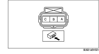
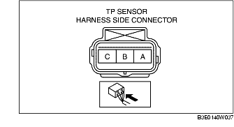
2. Disconnect the TP sensor connector.
3. Verify that the resistance between TP sensor terminals A and B changes moderately corresponding to the throttle valve openings.
-
• If it can be verified, go to the next step.
-
• If it cannot be verified, replace the TP sensor.
4. Measure the resistance between TP sensor terminals A and C.
-
• If within the specification, perform the "Circuit Open/Short Inspection", and repair or replace the malfunctioning part if necessary.
-
• If not within the specification, replace the TP sensor.
-
Resistance
-
3.0-5.0 kilohm (23°C {73 °F})
Circuit Open/Short Inspection
1. Disconnect the PCM connector. (See PCM REMOVAL/INSTALLATION [LF, L3].)
2. Inspect the following wiring harnesses for open or short. (Continuity check)
Open circuit
-
• If there is no continuity, the circuit is open. Repair or replace the harness.
-
- TP sensor terminal A and PCM terminal 2AA
-
- TP sensor terminal B and PCM terminal 2I
-
- TP sensor terminal C and PCM terminal 2W
Short circuit
-
• If there is continuity, the circuit is shorted. Repair or replace the harness.
-
- TP sensor terminal C and power supply
-
- TP sensor terminal C and body GND
-
- TP sensor terminal B and power supply
-
- TP sensor terminal B and body GND
-
- TP sensor terminal A and power supply