BAROMETRIC PRESSURE (BARO) SENSOR INSPECTION [LF, L3]
id0140a6818700
-
Note
-
• Before performing the following inspection, make sure to follow the procedure as indicated in the troubleshooting flowchart.
Voltage Inspection
1. Remove the BARO sensor with the connector still connected.
2. Turn the ignition switch to the ON position.
3. Verify that the voltage at PCM terminal 1AG (WDS PID: BARO) is within the specification.
-
• If not within the specification even though the related wiring harnesses have no malfunction, replace the BARO sensor.
-
BARO sensor output voltage
-
2.3-4.7 V
4. Disconnect the BARO sensor hose.
5. Install a vacuum pump to the BARO sensor.
6. Apply a vacuum of 30 kPa to the BARO sensor and verify that change in voltage at PCM terminal 1AG (WDS PID: BARO) is within the specification.
-
• If not within the specification, replace the BARO sensor.
-
BARO sensor output voltage variance
-
0.97-1.41 V
Circuit Open/Short Inspection
1. Disconnect the PCM connector. (See PCM REMOVAL/INSTALLATION [LF, L3].)
2. Inspect the following wiring harness for open or short. (Continuity check)
Open circuit
-
• If there is no continuity, the circuit is open. Repair or replace the harness.
-
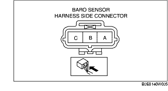
- Barometric pressure sensor terminal A and PCM terminal 1AG
-
- Barometric pressure sensor terminal B and PCM terminal 1AA
-
- Barometric pressure sensor terminal C and PCM terminal 1AE
Short circuit
-
• If there is continuity, the circuit is shorted. Repair or replace the harness.
-
- Barometric pressure sensor terminal C and power supply.
-
- Barometric pressure sensor terminal C and body GND.
-
- Barometric pressure sensor terminal A and power supply.
-
- Barometric pressure sensor terminal A and body GND