 |
am3zzw00009389
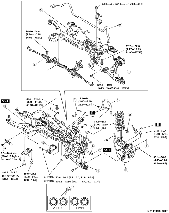
FRONT CROSSMEMBER REMOVAL/INSTALLATION
id021300801000
1. Remove in the order indicated in the table.
2. Install in the reverse order of removal.
3. Inspect the wheel alignment and adjust it if necessary. (See FRONT WHEEL ALIGNMENT.)
am3zzw00009389
|
|
1
|
Bolt (intermediate shaft)
|
|
2
|
Tie-rod end ball joint
|
|
3
|
Stabilizer control link upper nut
|
|
4
|
Lower arm ball joint
|
|
5
|
Pressure pipe (gear side)
|
|
6
|
Return hose (gear side)
|
|
7
|
Bolt
|
|
8
|
P/S angle sensor connector (with P/S angle sensor*)
|
|
9
|
Front crossmember component, steering gear and linkage component
|
|
10
|
No.1 engine mount rubber
|
|
11
|
Front stabilizer
|
|
12
|
Steering gear and linkage
|
|
13
|
Front lower arm
|
|
14
|
Front crossmember
|
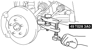
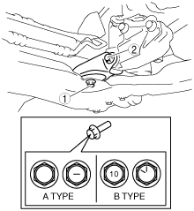
Tie-rod End Ball Joint Removal Note
1. Remove the tie-rod end locknut.
2. Detach the tie-rod end from the steering knuckle using the SST.
am3zzw00009390
|
P/S Angle Sensor Connector Removal Note
1. Remove the coolant reserve tank. (See COOLANT RESERVE TANK REMOVAL/INSTALLATION.)
2. Disconnect the P/S angle sensor connector.
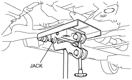
Front Crossmember Component, Steering Gear and Linkage Removal Note
1. Remove the front crossmember, front stabilizer, lower arm, and steering gear as a single unit using a jack.
am3zzw00009391
|
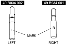
Front Crossmember Component, Steering Gear and Linkage Installation Note
1. Verify the left and right identification marks and install the positioning SST to the front crossmember.
am3zzw00009392
|
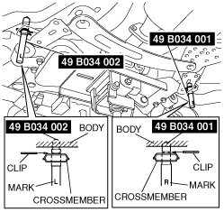
2. Support the front crossmember, front stabilizer, lower arm, and steering gear and linkage using a transmission jack.
am3zzw00009393
|
3. Raise the transmission jack gradually and install the front crossmember to the vehicle. At this point verify that the SST is securely inserted in the positioning holes on the body.
4. Tighten the front crossmember installation bolts and nuts.
5. Tighten the No.1 engine mount rubber installation bolt.
e3e213zsi999
|