Diagnostic procedure
|
STEP
|
INSPECTION
|
ACTION
|
|
|---|---|---|---|
|
1
|
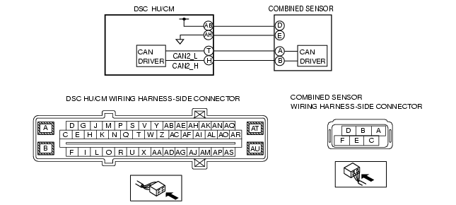
INSPECT COMBINED SENSOR POWER SUPPLY FOR OPEN CIRCUIT
• Turn the ignition switch to the ON position.
• Measure the voltage between the combined sensor terminal D and body ground.
• Is the voltage approx. 12 V?
|
Yes
|
Go to the next step.
|
|
No
|
Repair or replace the wiring harness, then go to Step 4.
|
||
|
2
|
INSPECT COMBINED SENSOR GROUND FOR OPEN CIRCUIT
• Turn the ignition switch off.
• Inspect for continuity between the combined sensor terminal E and body ground.
• Is there continuity?
|
Yes
|
Go to the next step.
|
|
No
|
Repair or replace the wiring harness, then go to Step 4.
|
||
|
3
|
INSPECT COMBINED SENSOR
• Inspect the combined sensor.
(See COMBINED SENSOR INSPECTION.)
• Is the combined sensor normal?
|
Yes
|
Go to the next step.
|
|
No
|
Replace the combined sensor, then go to the next step.
|
||
|
4
|
VERIFY THAT THE SAME DTC IS NOT PRESENT
• Clear the DTCs from the memory.
(See Clearing DTCs Procedures.)
• Start the engine and drive the vehicle at 10 km/h {6.2 mph} or more.
• Are the same DTCs present?
|
Yes
|
Repeat the inspection from Step 1.
If the malfunction recurs, replace the DSC CM, then go to the next step.
|
|
No
|
Go to the next step.
|
||
|
5
|
VERIFY THAT NO OTHER DTCS ARE PRESENT
• Are any other DTCs output?
|
Yes
|
Go to the applicable DTC inspection.
(See DTC Table.)
|
|
No
|
DTC troubleshooting completed.
|
||