Diagnostic procedure
|
STEP
|
INSPECTION
|
ACTION
|
|
|---|---|---|---|
|
1
|
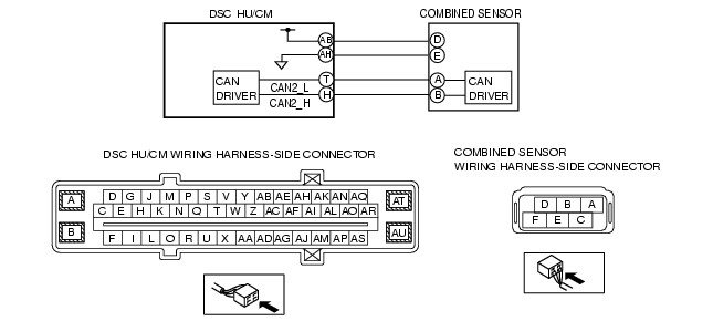
INSPECT COMBINED SENSOR SIGNAL (CAN2 LINE) FOR OPEN CIRCUIT
• Disconnect the DSC HU/CM connectors.
• Disconnect the combined sensor connectors.
• Inspect for continuity between the DSC HU/CM connectors (vehicle harness-side) and the following combined sensor connector terminals (vehicle harness-side):
• Is there continuity?
|
Yes
|
Go to the next step.
|
|
No
|
Repair or replace the wiring harness, then go to Step 4.
|
||
|
2
|
INSPECT COMBINED SENSOR SIGNAL (CAN2 LINE) FOR SHORT CIRCUIT
• Inspect for continuity between the following DSC HU/CM connector terminals (vehicle harness-side) and body ground:
• Is there continuity?
|
Yes
|
Repair or replace the wiring harness, then go to Step 4.
|
|
No
|
Go to the next step.
|
||
|
3
|
INSPECT THE COMBINED SENSOR
• Reconnect all disconnected connectors.
Inspect the combined sensor.
(See COMBINED SENSOR INSPECTION.)
• Is the combined sensor normal?
|
Yes
|
Go to the next step.
|
|
No
|
Replace the combined sensor, then go to the next step.
|
||
|
4
|
VERIFY THAT THE SAME DTC IS NOT PRESENT
• Clear the DTCs from the memory.
(See Clearing DTCs Procedures.)
• Are the same DTCs present?
|
Yes
|
Repeat the inspection from Step 1.
If the malfunction recurs, replace the DSC CM, then go to the next step.
|
|
No
|
Go to the next step.
|
||
|
5
|
VERIFY THAT NO OTHER DTCS ARE PRESENT
• Are any other DTCs output?
|
Yes
|
Go to the applicable DTC inspection.
(See DTC Table.)
|
|
No
|
DTC troubleshooting completed.
|
||