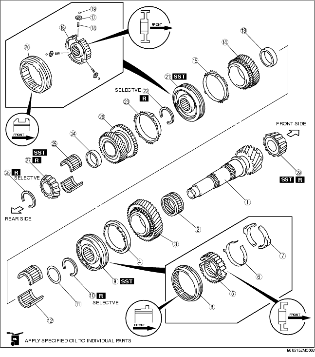
1. Assemble in the order shown in the figure.
|
1
|
Secondary shaft (No.2)
|
|
2
|
Reverse needle bearing
|
|
3
|
Reverse gear
|
|
4
|
Reverse synchronizer ring
|
|
5
|
Clutch hub
|
|
6
|
Spring
|
|
7
|
Synchronizer key
|
|
8
|
Clutch hub sleeve
|
|
9
|
Reverse clutch hub component
|
|
10
|
Snap ring
|
|
11
|
Spacer
|
|
12
|
5th needle bearing
|
|
13
|
Spacer
|
|
14
|
5th gear
|
|
15
|
5th synchronizer ring
|
|
16
|
Clutch hub
|
|
17
|
Synchronizer key
|
|
18
|
Spring
|
|
19
|
Steel ball
|
|
20
|
Clutch hub sleeve
|
|
21
|
5th/6th clutch hub component
|
|
22
|
Snap ring
|
|
23
|
6th synchronizer ring
|
|
24
|
Spacer
|
|
25
|
6th needle bearing
|
|
26
|
6th gear
|
|
27
|
Rear bearing
(See Rear Bearing Assembly Note.)
|
|
28
|
Snap ring
|
|
29
|
Front bearing
(See Front Bearing Assembly Note.)
|
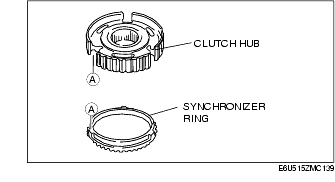
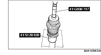
1. Assemble the reverse synchronizer ring, synchronizer key, key spring, and reverse clutch hub.
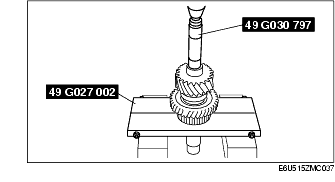
2. Using the SST and a press, install the reverse clutch hub component.
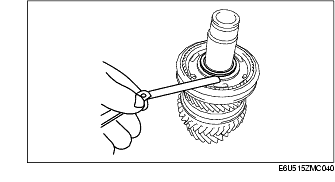
1. Install a new snap ring.
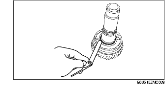
2. Measure the clearance between the reverse clutch hub and snap ring.
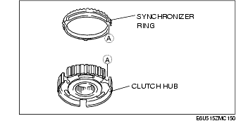
1. Install the 5th synchronizer ring and 5th/6th clutch hub.
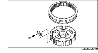
2. Assemble the synchronizer key, spring, steel ball, and clutch hub sleeve as shown in the figure.
3. Using the SST and a press, install the 5th/6th clutch hub component.
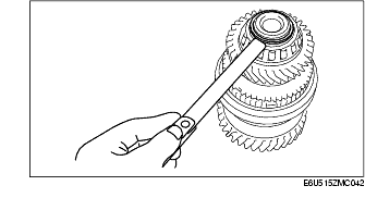
1. Install a new snap ring to the secondary shaft.
2. Measure the clearance between the snap ring and the 5th/6th clutch hub.
1. Place the 6th synchronizer ring.
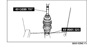
1. Install the SSTs and a press, and assemble the rear bearing.
1. Install a new snap ring to the secondary shaft.
2. Measure the clearance between the snap ring and the rear bearing inner race.
1. Using the SST and a press, install the front bearing.