 |
am6zzw00007350
ON-BOARD DIAGNOSTIC TEST [MZR-CD 2.2]
id0102f3801000
DTC Reading Procedure
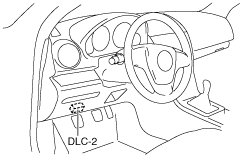
1. Connect the M-MDS (IDS) to the DLC-2.
am6zzw00007350
|
2. After the vehicle is identified, select the following items from the initialization screen of the IDS.
3. Then, select the “Retrieve CMDTCs” and perform procedures according to directions on the IDS screen.
4. Verify the DTC according to the directions on the IDS screen.
5. After completion of repairs, clear all DTCs stored in the PCM, while referring to “AFTER REPAIR PROCEDURE”.
Pending Trouble Code Access Procedure
1. Connect the M-MDS (IDS) to the DLC-2.
am6zzw00007350
|
2. After the vehicle is identified, select the following items from the initialization screen of the IDS.
3. Then, select the “Retrieve CMDTCs” and perform procedures according to directions on the IDS screen.
4. Retrieve the pending trouble codes according to the directions on the IDS screen.
Freeze Frame PID Data Access Procedure
1. Connect the M-MDS (IDS) to the DLC-2.
am6zzw00007350
|
2. After the vehicle is identified, select the following items from the initialization screen of the IDS.
3. Then, select the “Retrieve CMDTCs” and perform procedures according to directions on the IDS screen.
4. Retrieve the freeze frame PID data according to the directions on the IDS screen.
Freeze frame data table
|
Freeze frame data item |
Unit |
Description |
Corresponding PID data monitor item |
|---|---|---|---|
|
LOAD
|
%
|
Ratio of current intake air amount to wide open throttle engine operation intake-air amount
|
LOAD
|
|
ECT
|
°C, °F
|
Engine coolant temperature
|
ECT
|
|
MAP
|
KPa, Bar, in Hg
|
Manifold absolute pressure
|
MAP
|
|
RPM
|
RPM
|
Engine speed
|
RPM
|
|
VSS
|
KPH, MPH
|
Vehicle speed input from ABS/DSC HU/CM
|
VSS
|
|
BAT
|
°C, °F
|
Intake air temperature after super charged
|
BAT
|
|
MAF
|
g/Sec
|
Mass airflow of intake-air
|
MAF
|
|
TP
|
%
|
Intake shutter valve position
|
ISV_POS
|
|
FRP
|
KPa, Bar, psi
|
Fuel pressure at common rail
|
FRP
|
|
EQ_RAT11
|
—
|
Ratio of consumed air amount based on engine operation and theoretical air amount
|
—
|
|
O2S11
|
V
|
A/F sensor output voltage
|
—
|
|
WARMUPS
|
—
|
Number of warm-up cycles after all stored DTCs cleared
|
—
|
|
CLR_DIST
|
Km, mi
|
Mileage after all stored DTCs cleared
|
—
|
|
BARO
|
KPa, Bar, psi
|
Barometric pressure
|
BARO
|
|
EQ_RAT11
|
—
|
Ratio of consumed air amount based on engine operation and theoretical air amount
|
EQ_RAT11
|
|
O2S11
|
A
|
A/F sensor output current
|
O2S11
|
|
CATTEMP11
|
°C, °F
|
Exhaust gas temperature sensor No.1 value
|
EXHTEMP1
|
|
CATTEMP21
|
°C, °F
|
Exhaust gas temperature sensor No.2 value
|
EXHTEMP2
|
|
VPWR
|
V
|
PCM power supply voltage
|
VPWR
|
|
AAT
|
°C, °F
|
Intake air temperature
|
IAT
|
|
APP_D
|
%
|
APP sensor No.1 value
|
APP1
|
|
APP_E
|
%
|
APP sensor No.2 value
|
APP2
|
|
TAC_PCT
|
%
|
Target intake shutter valve opening angle calculated from engine operating conditions
|
ISV_DSD
|
Snapshot data table
|
Snapshot data item |
Unit |
Description |
Corresponding PID data monitor item |
|---|---|---|---|
|
LOAD
|
%
|
Ratio of current intake air amount to wide open throttle engine operation intake air amount
|
LOAD
|
|
ECT
|
°C, °F
|
Engine coolant temperature
|
ECT
|
|
MAP
|
KPa, Bar, in Hg
|
Manifold absolute pressure
|
MAP
|
|
RPM
|
RPM
|
Engine speed
|
RPM
|
|
VSS
|
KPH, MPH
|
Vehicle speed input from ABS/DSC HU/CM
|
VSS
|
|
BAT
|
°C, °F
|
Intake air temperature after super charged
|
BAT
|
|
MAF
|
g/sec
|
Mass airflow of intake-air
|
MAF
|
|
ISV_POS
|
%
|
Intake shutter valve position
|
ISV_POS
|
|
FRP
|
KPa, Bar, psi
|
Fuel pressure at common rail
|
FRP
|
|
O2S11
|
V
|
A/F sensor output voltage
|
—
|
|
A
|
A/F sensor output current
|
O2S11
|
|
|
CLR_CNT
|
—
|
Number of warm-up cycles after all stored DTCs cleared
|
—
|
|
CLR_DIST
|
Km, mi
|
Mileage after all stored DTCs cleared
|
—
|
|
BARO
|
KPa, Bar, psi
|
Barometric pressure
|
BARO
|
|
EQ_RAT11
|
—
|
Ratio of consumed air amount based on engine operation and theoretical air amount
|
EQ_RAT11
|
|
EXHTEMP1
|
°C, °F
|
Exhaust gas temperature sensor No.1 value
|
EXHTEMP1
|
|
EXHTEMP2
|
°C, °F
|
Exhaust gas temperature sensor No.2 value
|
EXHTEMP2
|
|
EXHTEMP3
|
°C, °F
|
Exhaust gas temperature sensor No.3 value
|
EXHTEMP3
|
|
VPWR
|
V
|
PCM power supply voltage
|
VPWR
|
|
IAT
|
°C, °F
|
Intake air temperature
|
IAT
|
|
APP1
|
%
|
APP sensor No.1 value
|
APP1
|
|
APP2
|
%
|
APP sensor No.2 value
|
APP2
|
|
ISV_DSD
|
%
|
Target intake shutter valve opening angle calculated from engine operating conditions
|
ISV_DSD
|
On-Board System Readiness Tests Access Procedure
1. Connect the M-MDS (IDS) to the DLC-2.
am6zzw00007350
|
2. After the vehicle is identified, select the following items from the initialization screen of the IDS.
3. Then, select the “***SUP” and “**EVAL” PIDs in the PID selection screen.
4. Monitor those PIDs and check it system monitor is completed.
PID/DATA Monitor and Record Procedure
1. Connect the M-MDS (IDS) to the DLC-2.
am6zzw00007350
|
2. After the vehicle is identified, select the following items from the initialization screen of the IDS.
3. Select the applicable PID from the PID table.
4. Verify the PID data according to the detections on the screen.
Diagnostic Monitoring Test Results Access Procedure
1. Connect the M-MDS (IDS) to the DLC-2.
am6zzw00007350
|
2. After the vehicle is identified, select the following items from the initialization screen of the IDS.
3. Verify the diagnostic monitoring test result according to the directions on the IDS screen.
Active Command Modes Procedure
1. Connect the M-MDS (IDS) to the DLC-2.
am6zzw00007350
|
2. After the vehicle is identified, select the following items from the initialization screen of the IDS.
3. Select the simulation items from the PID table.
4. Perform the active command modes function, inspect the operations for each parts.