 |
am6zzw00007719
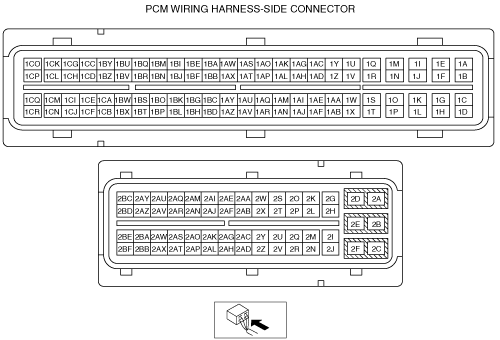
PCM INSPECTION [MZR-CD 2.2]
id0140f2802500
Without Using the M-MDS
Terminal voltage table (Reference)
am6zzw00007719
|
|
Terminal |
Signal |
Connected to |
Test condition |
Voltage (V) |
Inspection item |
|
|---|---|---|---|---|---|---|
|
1A
|
COMMON
|
Fuel injector No.2
|
Inspect using the wave Profile.
|
• Related wiring harness
• Fuel injector No.2
|
||
|
1B
|
COMMON
|
Fuel injector No.3
|
Inspect using the wave Profile.
|
• Related wiring harness
• Fuel injector No.3
|
||
|
1C
|
COMMON
|
Fuel injector No.4
|
Inspect using the wave Profile.
|
• Related wiring harness
• Fuel injector No.4
|
||
|
1D
|
COMMON
|
Fuel injector No.1
|
Inspect using the wave Profile.
|
• Related wiring harness
• Fuel injector No.1
|
||
|
1E
|
—
|
—
|
—
|
—
|
—
|
|
|
1F
|
Fuel injector No.3
|
Fuel injector No.3
|
Inspect using the wave Profile.
|
• Related wiring harness
• Fuel injector No.3
|
||
|
1G
|
—
|
—
|
—
|
—
|
—
|
|
|
1H
|
Fuel injector No.1
|
Fuel injector No.1
|
Inspect using the wave Profile.
|
• Related wiring harness
• Fuel injector No.1
|
||
|
1I
|
Fuel injector No.2
|
Fuel injector No.2
|
Inspect using the wave Profile.
|
• Related wiring harness
• Fuel injector No.2
|
||
|
1J
|
—
|
—
|
—
|
—
|
—
|
|
|
1K
|
Fuel injector No.4
|
Fuel injector No.4
|
Inspect using the wave Profile.
|
• Related wiring harness
• Fuel injector No.4
|
||
|
1L
|
—
|
—
|
—
|
—
|
—
|
|
|
1M
|
—
|
—
|
—
|
—
|
—
|
|
|
1N
|
—
|
—
|
—
|
—
|
—
|
|
|
1O
|
—
|
—
|
—
|
—
|
—
|
|
|
1P
|
—
|
—
|
—
|
—
|
—
|
|
|
1Q
|
—
|
—
|
—
|
—
|
—
|
|
|
1R
|
—
|
—
|
—
|
—
|
—
|
|
|
1S
|
—
|
—
|
—
|
—
|
—
|
|
|
1T
|
—
|
—
|
—
|
—
|
—
|
|
|
1U
|
Ground
|
Fuel injector No.2 shied wire
|
Under any condition
|
Below 1.0
|
• Related wiring harness
|
|
|
1V
|
MAF
|
MAF sensor
|
Switch the ignition to ON
|
Approx. 0.7
|
• Related wiring harness
• MAF sensor
|
|
|
Idle
|
Approx. 1.6
|
|||||
|
Engine speed 2,000 rpm
|
Approx. 2.4
|
|||||
|
1W
|
Ground
|
Fuel injector No.3 shied wire
|
Under any condition
|
Below 1.0
|
• Related wiring harness
|
|
|
1X
|
Refrigerant pressure switch (middle)
|
Refrigerant pressure switch (middle)
|
Refrigerant pressure is more than the specification. (Refrigerant pressure switch (middle) is on.)
|
Below 1.0
|
• Related wiring harness
• Refrigerant pressure switch (middle)
|
|
|
Refrigerant pressure is less than the specification. (Refrigerant pressure switch (middle) is off.)
|
Approx. 5.0
|
|||||
|
1Y
|
Ground
|
MAF sensor
|
Under any condition
|
Below 1.0
|
• Related wiring harness
• MAF sensor
|
|
|
1Z
|
Fuel temperature
|
Fuel temperature sensor
|
Switch the ignition to ON
|
Fuel temperature
40 °C {104 °F}
|
Approx. 1.6
|
• Related wiring harness
• Fuel temperature sensor
|
|
Fuel temperature
45 °C {113 °F}
|
Approx. 1.3
|
|||||
|
1AA
|
Ground
|
Fuel injector No.4 shied wire
|
Under any condition
|
Below 1.0
|
• Related wiring harness
|
|
|
1AB
|
—
|
—
|
—
|
—
|
—
|
|
|
1AC
|
Ground
|
Exhaust gas pressure sensor
|
Under any condition
|
Below 1.0
|
• Related wiring harness
• Exhaust gas pressure sensor
|
|
|
1AD
|
Exhaust gas pressure
|
Exhaust gas pressure sensor
|
Switch the ignition to ON
|
Approx. 1.0
|
• Related wiring harness
• Exhaust gas pressure sensor
|
|
|
Idle
|
Approx. 1.2
|
|||||
|
1AE
|
Ground
|
Fuel injector No.1 shied wire
|
Under any condition
|
Below 1.0
|
• Related wiring harness
|
|
|
1AF
|
Refrigerant pressure (low, high)
|
Refrigerant pressure switch (low pressure switch, high pressure switch)
|
Refrigerant pressure is more than the specification or less than the specification. (Refrigerant pressure switch (low pressure switch, high pressure switch) is off.)
|
Below 1.0
|
• Related wiring harness
• Refrigerant pressure switch (low pressure switch, high pressure switch)
|
|
|
Others
|
B+
|
|||||
|
1AG
|
—
|
—
|
—
|
—
|
—
|
|
|
1AH
|
EGR valve position
|
EGR valve position sensor
|
Switch the ignition to ON
|
Below 1.0
|
• Related wiring harness
• EGR valve
|
|
|
EGR valve opening angle 36.5%
|
Approx. 2
|
|||||
|
1AI
|
Ground
|
Boost sensor
|
Under any condition
|
Below 1.0
|
• Related wiring harness
• Boost sensor
|
|
|
1AJ
|
—
|
—
|
—
|
—
|
—
|
|
|
1AK
|
Ground
|
Exhaust gas temperature sensor No.1, No.2
|
Under any condition
|
Below 1.0
|
• Related wiring harness
• Exhaust gas temperature sensor No.1, No.2
|
|
|
1AL
|
Exhaust gas temp No.1
|
Exhaust gas temperature sensor No.1
|
Exhaust gas temperature 50 °C {122 °F}
|
Approx. 5
|
• Related wiring harness
• Exhaust gas temperature sensor No.1
|
|
|
1AM
|
Ground
|
Auto cruise switch
|
Under any condition
|
Below 1.0
|
• Related wiring harness
• Auto cruise switch
|
|
|
1AN
|
—
|
—
|
—
|
—
|
—
|
|
|
1AO
|
—
|
—
|
—
|
—
|
—
|
|
|
1AP
|
Exhaust gas temp No.2
|
Exhaust gas temperature sensor No.2
|
Exhaust gas temperature 50 °C {122 °F}
|
Approx. 5
|
• Related wiring harness
• Exhaust gas temperature sensor No.2
|
|
|
1AQ
|
Ground
|
Guide blade actuator position sensor
|
Under any condition
|
Below 1.0
|
• Related wiring harness
• Guide blade actuator position sensor
|
|
|
1AR
|
—
|
—
|
—
|
—
|
—
|
|
|
1AS
|
—
|
—
|
—
|
—
|
—
|
|
|
1AT
|
—
|
—
|
—
|
—
|
—
|
|
|
1AU
|
Glow
|
Glow plug
|
15s from 20 °C {68 °F} or less in water temperature and Switch the ignition to ON
|
B+
|
• Related wiring harness
• Glow plug
• Glow plug relay
|
|
|
Engine running after warm up
|
Below 1.0
|
|||||
|
1AV
|
—
|
—
|
—
|
—
|
—
|
|
|
1AW
|
Ground
|
Exhaust gas pressure correction temperature sensor
|
Under any condition
|
Below 1.0
|
• Related wiring harness
• Exhaust gas pressure correction temperature sensor
|
|
|
1AX
|
Exhaust gas pressure correction temperature
|
Exhaust gas pressure correction temperature sensor
|
Switch the ignition to ON
|
Near temperature of sensor 20 °C {68 °F}
|
Approx. 2.3
|
• Related wiring harness
• Exhaust gas pressure correction temperature sensor
|
|
Near temperature of sensor 80 °C {176 °F}
|
Approx. 0.5
|
|||||
|
1AY
|
MAP
|
Boost sensor
|
Switch the ignition to ON
|
Approx. 1.1
|
• Related wiring harness
• Boost sensor
|
|
|
Idle
|
Approx. 0.7
|
|||||
|
1AZ
|
Sedimentor
|
Sedimentor switch
|
Sedimentor switch ON
|
Below 1.0
|
• Related wiring harness
• Sedimentor switch
|
|
|
Sedimentor switch OFF
|
B+
|
|||||
|
1BA
|
Ground
|
IAT sensor No.2
|
Under any condition
|
Below 1.0
|
• Related wiring harness
• IAT sensor No.2
|
|
|
1BB
|
IAT
|
IAT sensor No.2
|
Switch the ignition to ON
|
IAT 30 °C
{86 °F}
|
Approx. 1.9
|
• Related wiring harness
• IAT sensor No.2
|
|
IAT 40 °C
{104 °F}
|
Approx. 1.47
|
|||||
|
1BC
|
Auto cruise
|
Auto cruise switch
|
OFF switch pressed in
|
Approx. 0
|
• Related wiring harness
• Auto cruise switch
|
|
|
Cancel switch pressed in
|
Approx. 1.0
|
|||||
|
Set (-) switch pressed in
|
Approx. 1.9
|
|||||
|
Set (+) switch pressed in
|
Approx. 2.7
|
|||||
|
RESUME switch pressed in
|
Approx. 3.4
|
|||||
|
ON switch pressed in
|
Approx. 4.0
|
|||||
|
1BD
|
Generator field coil control
|
Generator
|
Inspect using the wave Profile.
|
• Related wiring harness
• Generator
|
||
|
1BE
|
Ground
|
ECT sensor, Fuel temperature sensor, Intake shutter valve, EGR valve
|
Under any condition
|
Below 1.0
|
• Related wiring harness
• ECT sensor
• Fuel temperature sensor
• Intake shutter valve
• EGR valve
|
|
|
1BF
|
ECT
|
ECT sensor
|
Switch the ignition to ON
|
ECT 30 °C
{86 °F}
|
Approx. 2.61
|
• Related wiring harness
• ECT sensor
|
|
ECT 50 °C
{122 °F}
|
Approx. 1.72
|
|||||
|
ECT 60 °C
{140 °F}
|
Approx. 1.41
|
|||||
|
ECT 80 °C
{176 °F}
|
Approx. 0.88
|
|||||
|
1BG
|
—
|
—
|
—
|
—
|
—
|
|
|
1BH
|
—
|
—
|
—
|
—
|
—
|
|
|
1BI
|
Ground
|
Fuel pressure sensor
|
Under any condition
|
Below 1.0
|
• Related wiring harness
• Fuel pressure sensor
|
|
|
1BJ
|
Fuel pressure
|
Fuel pressure sensor
|
Switch the ignition to ON
|
Approx. 0.9
|
• Related wiring harness
• Fuel pressure sensor
|
|
|
Idle
|
Approx. 1.4
|
|||||
|
Engine speed is 2,000 rpm
|
Approx. 1.7
|
|||||
|
1BK
|
Generator output voltage
|
Generator
|
Inspect using the wave Profile.
|
• Related wiring harness
|
||
|
1BL
|
—
|
—
|
—
|
—
|
—
|
|
|
1BM
|
Ground
|
Fuel pressure sensor shild wire
|
Under any condition
|
Below 1.0
|
• Related wiring harness
• Fuel pressure sensor
|
|
|
1BN
|
—
|
—
|
—
|
—
|
—
|
|
|
1BO
|
—
|
—
|
—
|
—
|
—
|
|
|
1BP
|
VBC solenoid valve
|
VBC solenoid valve
|
Inspect using the wave Profile.
|
• Related wiring harness
• VBC solenoid valve
|
||
|
1BQ
|
CMP (G-)
|
CMP sensor
|
Idle
|
Below 1.0
|
• Related wiring harness
• CMP sensor
|
|
|
1BR
|
CMP (G+)
|
CMP sensor
|
Inspect using the wave Profile.
|
• Related wiring harness
• CMP sensor
|
||
|
1BS
|
Guide blade actuator position
|
Guide blade actuator position sensor
|
Switch the ignition to ON
|
Below 1.0
|
• Related wiring harness
• Guide blade actuator position sensor
|
|
|
Idle
|
Approx. 4.5
|
|||||
|
Engine speed is 3,000 rpm
|
Approx. 3.0
|
|||||
|
1BT
|
Glow
|
Glow plug relay
|
15 s from when switch the ignition to ON position with ECT at 20 °C {68 °F} or less
|
B+
|
• Related wiring harness
• Glow plug relay
|
|
|
Idle
|
Below 1.0
|
|||||
|
1BU
|
CKP (NE-)
|
CKP sensor
|
Idle
|
Below 1.0
|
• Related wiring harness
• CKP sensor
|
|
|
1BV
|
CKP (NE+)
|
CKP sensor
|
Inspect using the wave Profile.
|
• Related wiring harness
• CKP sensor
|
||
|
1BW
|
Cooling fan control
|
Cooling fan relay No.4
|
Cooling fan relay No.4 operating
|
Below 1.0
|
• Related wiring harness
• Cooling fan relay No.4
|
|
|
Cooling fan relay No.4 not operating
|
B+
|
|||||
|
1BX
|
A/C
|
A/C relay
|
A/C operating
|
Below 1.0
|
• Related wiring harness
• A/C relay
|
|
|
A/C not operating
|
B+
|
|||||
|
1BY
|
Constant voltage (Vref)
|
CMP sensor
|
Switch the ignition to ON
|
Approx. 5
|
• Related wiring harness
• CMP sensor
|
|
|
1BZ
|
—
|
—
|
—
|
—
|
—
|
|
|
1CA
|
Cooling fan control
|
Cooling fan relay No.1
|
Cooling fan relay No.1 operating
|
Below 1.0
|
• Related wiring harness
• Cooling fan relay No.1
|
|
|
Cooling fan relay No.1 not operating
|
B+
|
|||||
|
1CB
|
Starter
|
Ignition switch, Starter relay, Starter inter lock switch
|
Cranking
|
Below 1.0
|
• Related wiring harness
• Ignition switch
• Starter relay
• Starter inter lock switch
• Main fuse
|
|
|
1CC
|
Constant voltage (Vref)
|
EGR valve, Intake shutter valve, CKP sensor
|
Switch the ignition to ON
|
Approx. 5
|
• Related wiring harness
• EGR valve
• Intake shutter valve
• CKP sensor
|
|
|
1CD
|
Constant voltage (Vref)
|
Exhaust gas pressure sensor
|
Switch the ignition to ON
|
Approx. 5
|
• Related wiring harness
• Exhaust gas pressure sensor
|
|
|
1CE
|
—
|
—
|
—
|
—
|
—
|
|
|
1CF
|
Cooling fan control
|
Cooling fan relay No.2, No.3
|
Cooling fan relay No.2, No.3 operating
|
Below 1.0
|
• Related wiring harness
• Cooling fan relay No.2, No.3
|
|
|
Cooling fan relay No.2, No.3 not operating
|
B+
|
|||||
|
1CG
|
—
|
—
|
—
|
—
|
—
|
|
|
1CH
|
Constant voltage (Vref)
|
Fuel pressure sensor
|
Switch the ignition to ON
|
Approx. 5
|
• Related wiring harness
• Fuel pressure sensor
|
|
|
1CI
|
—
|
—
|
—
|
—
|
—
|
|
|
1CJ
|
EGR cooler bypass valve solenoid valve
|
EGR cooler bypass valve solenoid valve
|
Switch the ignition to ON
|
B+
|
• Related wiring harness
• EGR cooler bypass valve solenoid valve
|
|
|
Idle
|
Below 1.0
|
|||||
|
1CK
|
—
|
—
|
—
|
—
|
—
|
|
|
1CL
|
Constant voltage (Vref)
|
Boost sensor
|
Switch the ignition to ON
|
Approx. 5
|
• Related wiring harness
• Boost sensor
|
|
|
1CM
|
—
|
—
|
—
|
—
|
—
|
|
|
1CN
|
—
|
—
|
—
|
—
|
—
|
|
|
1CO
|
—
|
—
|
—
|
—
|
—
|
|
|
1CP
|
Constant voltage (Vref)
|
Guide blade actuator position sensor
|
Switch the ignition to ON
|
Approx. 5
|
• Related wiring harness
• Guide blade actuator position sensor
|
|
|
1CQ
|
—
|
—
|
—
|
—
|
—
|
|
|
1CR
|
—
|
—
|
—
|
—
|
—
|
|
|
2A
|
Ground
|
Body ground
|
Under any condition
|
Below 1.0
|
• Related wiring harness
|
|
|
2B
|
Ground
|
Body ground
|
Under any condition
|
Below 1.0
|
• Related wiring harness
|
|
|
2C
|
B+
|
Main relay
|
Main relay ON
|
B+
|
• Related wiring harness
• Main relay
|
|
|
Main relay OFF
|
Below 1.0
|
|||||
|
2D
|
Ground
|
Body ground
|
Under any condition
|
Below 1.0
|
• Related wiring harness
|
|
|
2E
|
Ground
|
Body ground
|
Under any condition
|
Below 1.0
|
• Related wiring harness
|
|
|
2F
|
B+
|
Main relay
|
Main relay ON
|
B+
|
• Related wiring harness
• Main relay
|
|
|
Main relay OFF
|
Below 1.0
|
|||||
|
2G
|
Suction control valve
|
Suction control valve
|
Under any condition
|
Below 1.0
|
• Related wiring harness
• Suction control valve
|
|
|
2H
|
Suction control valve
|
Suction control valve
|
Inspect using the wave Profile.
|
• Related wiring harness
• Suction control valve
|
||
|
2I
|
Main relay control
|
Main relay
|
Switch the ignition to ON
|
Below 1.0
|
• Related wiring harness
• Main relay
|
|
|
Switch the ignition to OFF
|
B+
|
|||||
|
2J
|
Back-up power supply
|
Battery, Generator
|
Under any condition
|
B+
|
• Related wiring harness
• Battery
• Generator
|
|
|
2K
|
—
|
—
|
—
|
—
|
—
|
|
|
2L
|
—
|
—
|
—
|
—
|
—
|
|
|
2M
|
—
|
—
|
—
|
—
|
—
|
|
|
2N
|
IG
|
Ignition switch
|
Switch the ignition to ON and Start position
|
B+
|
• Related wiring harness
|
|
|
Switch the ignition to other position
|
Below 1.0
|
|||||
|
2O
|
—
|
—
|
—
|
—
|
—
|
|
|
2P
|
—
|
—
|
—
|
—
|
—
|
|
|
2Q
|
—
|
—
|
—
|
—
|
—
|
|
|
2R
|
—
|
—
|
—
|
—
|
—
|
|
|
2S
|
Constant voltage (Vref)
|
APP sensor
|
Switch the ignition to ON
|
Approx. 5
|
• Related wiring harness
• APP sensor
|
|
|
2T
|
Constant voltage (Vref)
|
APP sensor
|
Switch the ignition to ON
|
Approx. 5
|
• Related wiring harness
• APP sensor
|
|
|
2U
|
—
|
—
|
—
|
—
|
—
|
|
|
2V
|
—
|
—
|
—
|
—
|
—
|
|
|
2W
|
APP
|
APP sensor
|
Accelerator pedal released
|
Approx. 0.7
|
• Related wiring harness
• APP sensor
|
|
|
Accelerator pedal depressed
|
Approx. 4.0
|
|||||
|
2X
|
APP
|
APP sensor
|
Accelerator pedal released
|
Approx. 0.4
|
• Related wiring harness
• APP sensor
|
|
|
Accelerator pedal depressed
|
Approx. 2.0
|
|||||
|
2Y
|
—
|
—
|
—
|
—
|
—
|
|
|
2Z
|
—
|
—
|
—
|
—
|
—
|
|
|
2AA
|
Ground
|
APP sensor
|
Under any condition
|
Below 1.0
|
• Related wiring harness
• APP sensor
|
|
|
2AB
|
Ground
|
APP sensor
|
Under any condition
|
Below 1.0
|
• Related wiring harness
• APP sensor
|
|
|
2AC
|
—
|
—
|
—
|
—
|
—
|
|
|
2AD
|
CAN (H)
|
Instrument cluster, ABS HU/CM, DSC HU/CM
|
Because this terminal is for CAN, good/no good judgment by terminal voltage is not possible
|
• Related wiring harness
|
||
|
2AE
|
A/F
|
A/F sensor
|
Idle
|
Approx. 2.2
|
• Related wiring harness
• A/F sensor
|
|
|
2AF
|
A/F
|
A/F sensor
|
Idle
|
0↔1
|
• Related wiring harness
• A/F sensor
|
|
|
2AG
|
—
|
—
|
—
|
—
|
—
|
|
|
2AH
|
CAN (L)
|
Instrument cluster, ABS HU/CM, DSC HU/CM
|
Because this terminal is for CAN, good/no good judgment by terminal voltage is not possible
|
• Related wiring harness
|
||
|
2AI
|
—
|
—
|
—
|
—
|
—
|
|
|
2AJ
|
—
|
—
|
—
|
—
|
—
|
|
|
2AK
|
Brake signal 2
|
Brake switch (No.2 signal)
|
Brake pedal depressed
|
B+
|
• Related wiring harness
• Brake switch (No.2 signal)
|
|
|
Brake pedal released
|
Below 1.0
|
|||||
|
2AL
|
Clutch
|
Clutch switch
|
Clutch pedal depressed
|
Below 1.0
|
• Related wiring harness
• Clutch switch
|
|
|
Clutch pedal released
|
B+
|
|||||
|
2AM
|
Ground
|
MAF/IAT sensor
|
Under any condition
|
Below 1.0
|
• Related wiring harness
• MAF/IAT sensor
|
|
|
2AN
|
IAT
|
MAF/IAT sensor
|
Switch the ignition to ON
|
IAT 30 °C
{86 °F}
|
Approx. 1.9
|
• Related wiring harness
• MAF/IAT sensor
|
|
IAT 40 °C
{104 °F}
|
Approx. 1.47
|
|||||
|
2AO
|
Brake signal 1
|
Brake switch (No.1 signal)
|
Brake pedal depressed
|
Below 1.0
|
• Related wiring harness
• Brake switch (No.1 signal)
|
|
|
Brake pedal released
|
B+
|
|||||
|
2AP
|
Starter
|
Ignition switch, Starter relay
|
Switch the ignition to START position
|
B+
|
• Related wiring harness
• Ignition switch
• Starter relay
|
|
|
Except for Switch the ignition to START position
|
Below 1.0
|
|||||
|
2AQ
|
—
|
—
|
—
|
—
|
—
|
|
|
2AR
|
Intake shutter valve position
|
Intake shutter valve
|
Idle
|
Clutch pedal released
|
Approx. 0.75
|
• Related wiring harness
• Intake shutter valve
|
|
Clutch pedal depressed
|
Approx. 3.9
|
|||||
|
2AS
|
—
|
—
|
—
|
—
|
—
|
|
|
2AT
|
Neutral
|
Neutral switch
|
Neutral
|
Below 1.0
|
• Related wiring harness
• Neutral switch
|
|
|
Other
|
B+
|
|||||
|
2AU
|
—
|
—
|
—
|
—
|
—
|
|
|
2AV
|
—
|
—
|
—
|
—
|
—
|
|
|
2AW
|
—
|
—
|
—
|
—
|
—
|
|
|
2AX
|
—
|
—
|
—
|
—
|
—
|
|
|
2AY
|
—
|
—
|
—
|
—
|
—
|
|
|
2AZ
|
Ground
|
A/F sensor shield wire
|
Under any condition
|
Below 1.0
|
• Related wiring harness
|
|
|
2BA
|
Intake shutter valve (ISV-)
|
Intake shutter valve
|
Idle
|
0 ÛB+
|
• Related wiring harness
• Intake shutter valve
|
|
|
2BB
|
Intake shutter valve (ISV+)
|
Intake shutter valve
|
Idle
|
0 ÛB+
|
• Related wiring harness
• Intake shutter valve
|
|
|
2BC
|
—
|
—
|
—
|
—
|
—
|
|
|
2BD
|
A/F sensor heater
|
A/F sensor shield wire
|
Inspect using the wave Profile.
|
• Related wiring harness
• A/F sensor heater
|
||
|
2BE
|
EGR valve (EGR-)
|
EGR valve
|
Idle
|
Below 1.0
|
• Related wiring harness
• EGR valve
|
|
|
2BF
|
EGR valve (EGR+)
|
EGR valve
|
Inspect using the wave Profile.
|
• Related wiring harness
• EGR valve
|
||
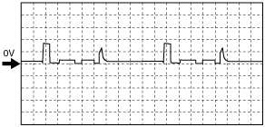
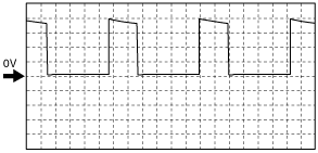
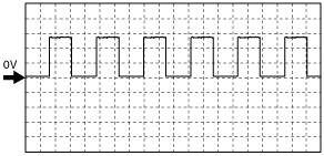
Inspection Using An Oscilloscope (Reference)
Common signal
am6zzw00007720
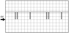
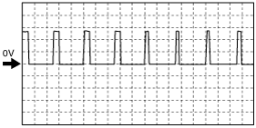
|
Fuel injection signal
am6zzw00007721
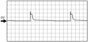
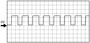
|
Generator field coil control signal
am6zzw00007722
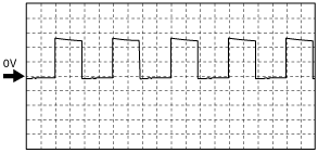
|
Generator signal
am6zzw00007723
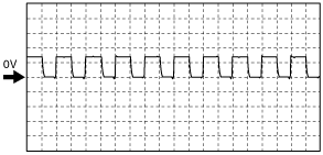
|
VBC solenoid valve signal
am6zzw00007724
|
CMP (G+) signal
am6zzw00007725
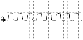
|
CKP (NE+) signal
am6zzw00007726
|
Suction control valve signal
am6zzw00007727
|
A/F sensor heater control signal
am6zzw00007728
|
EGR valve (EGR+) signal
am6zzw00007729
|
Using M-MDS
1. Connect the M-MDS to the DLC-2. (See ON-BOARD DIAGNOSTIC TEST [MZR-CD 2.2].)
am6zzw00000122
|
2. Measure the PID value.
3. Switch the ignition to ON.
PID/DATA monitor table (Reference)
|
Monitor item (Definition) |
Unit/Condition |
Condition/Specification (Reference) |
Inspection item |
PCM terminal |
|
|---|---|---|---|---|---|
|
AC_REQ
(A/C switch)
|
OFF/ON
|
Refrigerant pressure switch is off: Off
Others: On
|
A/C switch
|
1AF
|
|
|
ACCS
(Air conditioning compressor cycling switch)
|
OFF/ON
|
A/C switch ON and fan switch ON: On
Others: Off
|
Inspect following PIDs: AC_REQ, APP1, APP2, ECT, RPM
|
1BX
|
|
|
ALTF
(Generator field coil control duty signal)
|
%
|
Switch the ignition to ON: 0%
Idle: 0—100%
|
Inspect following PIDs:
IAT, ECT, RPM, VPWR, ALTT V
|
1BD
|
|
|
ALTT V
(Generator output voltage)
|
V
|
Switch the ignition to ON: 0 V
Idle: Approx. 10 V
|
Generator
|
1BK
|
|
|
APP
(Accelerator pedal position)
|
%
|
Accelerator pedal released: 0%
Accelerator pedal depressed: 100%
|
Inspect following PIDs:
APP1, APP2
|
2W, 2X
|
|
|
APP1
(Accelerator pedal position sensor 1)
|
%
|
Accelerator pedal released: 0%
Accelerator pedal depressed: 100%
|
APP sensor
|
2W
|
|
|
V
|
Accelerator pedal released:
Approx. 0.7 V
Accelerator pedal depressed:
Approx. 4.0 V
|
||||
|
APP2
(Accelerator pedal position sensor 2)
|
%
|
Accelerator pedal released: 0%
Accelerator pedal depressed: 100%
|
APP sensor
|
2X
|
|
|
V
|
Accelerator pedal released:
Approx. 0.4 V
Accelerator pedal depressed:
Approx. 2.0 V
|
||||
|
ARPMDES
(Target engine speed)
|
RPM
|
675—775 rpm
|
Inspect following PIDs:
IVS, AC_REQ, IAT, ECT, BOOST_DSD, FRP, RPM, VSS
|
—
|
|
|
BARO
(Barometric pressure)
|
KPa, Bar, psi
|
Indicate Barometric pressure.
|
BARO sensor
|
—
|
|
|
V
|
BARO 101.3 kPa: Approx. 3.6V
|
||||
|
BAT
(Intake Air Temperature)
|
°C, °F
|
Intake air temperature is display
|
IAT sensor No.2
|
1BB
|
|
|
BAT_V
(Intake Air Temperature sensor No.2)
|
V
|
30°C {86 °F}: Approx. 1.9 V
40°C {104 °F}: Approx. 1.47 V
|
|||
|
BOO
(Brake ON/OFF)
|
OFF/ON
|
Brake pedal released: Off
Brake pedal depressed: On
|
Brake switch (No.1 signal)
|
2AO
|
|
|
BOOST_DSD (Desired boost pressure)
|
KPa, Bar, psi
|
Desired boost pressure is displayed.
|
Perform applicable DTC troubleshooting.
|
—
|
|
|
CHRGLP
(Generator warning light)
|
OFF/ON
|
Switch the ignition to ON: On
Idle: Off
|
Perform applicable DTC troubleshooting.
|
—
|
|
|
COLP
(Refrigerant pressure switch (middle))
|
OFF/ON
|
Refrigerant pressure (middle) is more than the specification: ON
Refrigerant pressure (middle) is more than the specification: OFF
|
Refrigerant pressure switch (middle)
|
1X
|
|
|
CPP
|
OFF/ON
|
Clutch pedal released: Off
Clutch pedal depressed: On
|
CPP switch
|
2AL
|
|
|
DPF_LMP_CNT
|
—
|
Displays the number of diesel particulate filter indicator light illuminations.
|
—
|
—
|
|
|
DPF_REG_CNT
|
—
|
Displays the number of diesel particulate filter regenerations.
|
—
|
—
|
|
|
DSC_ACT
(DSC control enable/disable)
|
OFF/ON
|
Switch the ignition to ON: Off
|
—
|
—
|
|
|
Idle: On
|
|||||
|
ECT
(Engine coolant temperature)
|
°C, °F
|
Engine coolant temperature is displayed.
|
ECT sensor
|
1BF
|
|
|
V
|
ECT 30 °C {86 °F}: Approx. 2.61 V
ECT 50 °C {122 °F}: Approx. 1.72 V
ECT 60 °C {140 °F}: Approx. 1.41 V
ECT 80 °C {176 °F}: Approx. 0.88 V
|
||||
|
EGR_C_BP
(EGR cooler bypass valve)
|
OFF/ON
|
ON: ECT less than 65 °C {149 °F}, EXHTEMP less than 205 °C {401 °F}, RPM more than 500 rpm
OFF: Except above
|
EGR cooler bypass valve
|
1CJ
|
|
|
EGR_LRN
(EGR valve)
|
—
|
Displays EGR valve fully-closed learning value.
|
EGR valve
|
1AH
|
|
|
EGRP
(EGR valve)
|
V
|
EGR valve opening angle 14 %: Approx. 1.3 V
EGR valve opening angle 24 %: Approx. 1.6 V
|
EGR valve
|
||
|
mm
|
EGR valve opening angle 14%: Approx. 1.4 mm
EGR valve opening angle 24%: Approx. 2.4 mm
|
||||
|
%
|
Displays EGR valve opening angle.
|
||||
|
ENG_STAT
|
Cranking / Running / Stalled
|
Displays the engine conditions.
|
—
|
—
|
|
|
EQ_RAT11
(Equivalence Ratio (Lambda))
|
—
|
Idle: 1.99
|
Inspect following PIDs:
BAT, BAT_V, IAT, ECT, O2S11, O2S11_CAL, O2S11_MODE
|
2AE, 2AF
|
|
|
EXH_FL
|
—
|
Displays the exhaust gas flow amount.
|
—
|
—
|
|
|
EXHPRESS_DIF
(Exhaust gas pressure sensor)
|
KPa, Bar, psi
|
Indicates the difference in exhaust gas pressure before and after passing the diesel particulate filter.
|
Exhaust pressure sensor
|
1AD
|
|
|
V
|
|||||
|
EXHTEMP1
(Exhaust gas temperature sensor)
|
V
|
Indicate the exhaust gas temperature.
|
Exhaust gas temperature sensor No.1
|
1AL
|
|
|
°C, °F
|
|||||
|
EXHTEMP2
(Exhaust gas temperature sensor)
|
V
|
Indicate the exhaust gas temperature.
|
Exhaust gas temperature sensor No.2
|
1AP
|
|
|
°C, °F
|
|||||
|
FAN1
(FAN1 Control Signal)
|
OFF/ON
|
Cooling fan relay No.1 opening: ON
Cooling fan relay No.1 not opening: OFF
|
Cooling fan relay No.1
|
1CA
|
|
|
FAN2
(FAN2 Control Signal)
|
OFF/ON
|
Cooling fan relay No.4 opening: ON
Cooling fan relay No.4 not opening: OFF
|
Coolong fan relay No.4
|
1BW
|
|
|
FAN3
(FAN3 Control Signal)
|
OFF/ON
|
Cooling fan relay No.2, No.3 opening: ON
Cooling fan relay No.2, No.3 not opening: OFF
|
Coolong fan relay No.2, No.3
|
1CF
|
|
|
Fl_LRN_01
(Fuel injector No.1)
|
—
|
Fuel injection learning value (injector 1 at 35MPa)
|
Fuel injector No.1
|
1H
|
|
|
Fl_LRN_02
(Fuel injector No.2)
|
—
|
Fuel injection learning value (injector 2 at 35MPa)
|
Fuel injector No.2
|
1I
|
|
|
Fl_LRN_03
(Fuel injector No.3)
|
—
|
Fuel injection learning value (injector 3 at 35MPa)
|
Fuel injector No.3
|
1F
|
|
|
Fl_LRN_04
(Fuel injector No.4)
|
—
|
Fuel injection learning value (injector 4 at 35MPa)
|
Fuel injector No.4
|
1K
|
|
|
Fl_LRN_11
(Fuel injector No.1)
|
—
|
Fuel injection learning value (injector 1 at 65MPa)
|
Fuel injector No.1
|
1H
|
|
|
Fl_LRN_12
(Fuel injector No.2)
|
—
|
Fuel injection learning value (injector 2 at 65MPa)
|
Fuel injector No.2
|
1I
|
|
|
Fl_LRN_13
(Fuel injector No.3)
|
—
|
Fuel injection learning value (injector 3 at 65MPa)
|
Fuel injector No.3
|
1F
|
|
|
Fl_LRN_14
(Fuel injector No.4)
|
—
|
Fuel injection learning value (injector 4 at 65MPa).
|
Fuel injector No.4
|
1K
|
|
|
Fl_LRN_21
(Fuel injector No.1)
|
—
|
Fuel injection learning value (injector 1 at 100MPa)
|
Fuel injector No.1
|
1H
|
|
|
Fl_LRN_22
(Fuel injector No.2)
|
—
|
Fuel injection learning value (injector 2 at 100MPa)
|
Fuel injector No.2
|
1I
|
|
|
Fl_LRN_23
(Fuel injector No.3)
|
—
|
Fuel injection learning value (injector 3 at 100MPa)
|
Fuel injector No.3
|
1F
|
|
|
Fl_LRN_24
(Fuel injector No.4)
|
—
|
Fuel injection learning value (injector 4 at 100MPa)
|
Fuel injector No.4
|
1K
|
|
|
Fl_LRN_31
(Fuel injector No.1)
|
—
|
Fuel injection learning value (injector 1 at 140MPa)
|
Fuel injector No.1
|
1H
|
|
|
Fl_LRN_32
(Fuel injector No.2)
|
—
|
Fuel injection learning value (injector 2 at 140MPa)
|
Fuel injector No.2
|
1I
|
|
|
Fl_LRN_33
(Fuel injector No.3)
|
—
|
Fuel injection learning value (injector 3 at 140MPa)
|
Fuel injector No.3
|
1F
|
|
|
Fl_LRN_34
(Fuel injector No.4)
|
—
|
Fuel injection learning value (injector 4 at 140MPa)
|
Fuel injector No.4
|
1K
|
|
|
FIA_DSD
(Fuel injector)
|
—
|
Indicate the desired injector correction.
|
Fuel injector
|
—
|
|
|
FIP_FL
(Supply pump flow control)
|
A
|
Idle: Approx. 1.8 A
|
Inspect following PIDs:
AC_REQ, BAT, BAT_V, ECT, BOOST_DSD, FRP, IVS, IAT, RPM, VSS
|
—
|
|
|
FIP_FL_DSD
(Supply pump flow desired)
|
—
|
Switch the ignition to ON: Approx. 0 mm3/stroke
Idle: Approx. 20 mm3/stroke
|
Inspect following PIDs:
AC_REQ, BAT, BAT_V, ECT, BOOST_DSD, FRP, IVS, IAT, RPM, VSS
|
—
|
|
|
FIP_LRN
(Supply pump learning amount)
|
NOT_LRN / TMP_LRN / CMP_LRN
|
Indicate the supply pump learning amount.
|
Inspect following PIDs:
AC_REQ, BAT, BAT_V, ECT, BOOST_DSD, FRP, IVS, IAT, RPM, VSS
|
—
|
|
|
A
|
|||||
|
FIP_SCV
(Supply pump suction control valve)
|
A
|
Switch the ignition to ON: Approx. 0 mA
Idle: 1.67—1.73 A
|
Inspect following PIDs:
AC_REQ, BAT, BAT_V, ECT, BOOST_DSD, FRP, IVS, IAT, RPM, VSS
|
2G, 2H
|
|
|
FLT
(Fuel temperature)
|
°C, °F
|
Fuel temperature is displayed.
|
Fuel temperature sensor
|
1Z
|
|
|
FP
(Fuel pump relay)
|
%
|
Idle: Approx. 45%
|
Inspect following PIDs: RPM
|
—
|
|
|
FRP
(Fuel pressure sensor)
|
V
|
Switch the ignition to ON: Approx. 0.9 V
|
Fuel pressure sensor
|
1BJ
|
|
|
Idle: Approx. 1.4 V
2,000 rpm: Approx. 1.7 V
|
|||||
|
KPa, Bar, psi
|
Switch the ignition to ON: 0 kPa {0 kgf/cm2, 0 psi}
|
||||
|
Idle: Approx. 38 MPa {387 kgf/cm2, 5,511 psi}
2,000 rpm: Approx. 48 MPa {489 kgf/cm2, 6,962 psi}
|
|||||
|
FRP_DSD
|
KPa, Bar, psi
|
Switch the ignition to ON: 0 kPa {0 kgf/cm2, 0 psi}
Idle: Approx. 35 MPa {357 kgf/cm2, 5,076 psi}
|
|||
|
GENVDSD
(Generator voltage desired)
|
V
|
Indicate the generator voltage desired.
|
Perform applicable DTC troubleshooting.
|
—
|
|
|
GP_LMP
(Glow indicator light)
|
OFF/ON
|
Glow indicator light Off: Off
Glow indicator light ON: On
|
Inspect following PIDs:
ECT, BOOST_DSD, VSS
|
1BT
|
|
|
GPC
(Glow plug control)
|
OFF/ON
|
Switch the ignition to ON: Off
|
|||
|
Cranking: On
Idle: Off
|
|||||
|
HTR11
(A/F sensor heater control)
|
%
|
Switch the ignition to ON: 0%
|
Inspect following PIDs:
BAT, BAT_V, IAT, MAF, ECT, RPM
|
2BD
|
|
|
IAT
(Intake air temperature)
|
V
|
30°C {86 °F}: Approx. 1.9 V
40°C {104 °F}: Approx. 1.47 V
|
IAT sensor
|
2AN
|
|
|
°C, °F
|
Intake air temperature is display
|
||||
|
INGEAR
(in gear)
|
OFF/ON
|
When the following conditions are satisfied: On
• Not neutral
Except above: Off
|
Neutral switch
|
2AT
|
|
|
INJ_LRN_F1
|
—
|
Displays the cause of the fuel injection amount learning error.
|
—
|
—
|
|
|
INJ_LRN_F2
|
—
|
Displays the cause of the fuel injection amount learning error.
|
—
|
—
|
|
|
INJ1_CMP
|
— (mm3/stroke)
|
Dispays the fuel injector No.1 correction value
|
Fuel injector No.1
|
1H
|
|
|
INJ2_CMP
|
— (mm3/stroke)
|
Dispays the fuel injector No.2 correction value
|
Fuel injector No.2
|
1I
|
|
|
INJ3_CMP
|
— (mm3/stroke)
|
Dispays the fuel injector No.3 correction value
|
Fuel injector No.3
|
1F
|
|
|
INJ4_CMP
|
— (mm3/stroke)
|
Dispays the fuel injector No.4 correction value
|
Fuel injector No.4
|
1K
|
|
|
ISV_ACT
(Intake Shatter Valve Control Actual)
|
°
|
Switch the ignition to ON: Approx. 89°
Idle: 4 °
|
Intake shutter valve
|
2AR
|
|
|
ISV_DSD
(Intake Shatter Valve Control Desired)
|
°
|
Switch the ignition to ON: Approx. 4 °
Idle: Approx. 80°
|
Intake shutter valve
|
||
|
%
|
Switch the ignition to ON: Approx. 6.7%
Idle: Approx. 80%
|
||||
|
ISV_LRN_C
(Intake Shatter Valve Learning Value - Closed)
|
°
|
Idle: Approx. -0.23 °
|
Intake shutter valve
|
||
|
ISV_POS
(Intake Shatter Valve Position)
|
V
|
Switch the ignition to ON: Approx. 4.1 V
Idle: Approx. 0.7 V
|
Intake shutter valve
|
||
|
%
|
Switch the ignition to ON: Approx. 88%
Idle: Approx. 3.5 %
|
||||
|
IVS
|
Idle / Off Idle
|
Idle: Idle
Except above: Off Idle
|
—
|
—
|
|
|
LOAD
(Engine load)
|
%
|
Switch the ignition to ON: 0%
Idle: Approx. 8.62%
|
—
|
—
|
|
|
MAF
(Mass Air Flow)
|
g/sec
|
Switch the ignition to ON: 0 g/s
Idle: Approx. 13 g/s
2,000 rpm: Approx. 21 g/s
|
MAF sensor
|
1V
|
|
|
V
|
Switch the ignition to ON: Approx. 0.8 V
Idle: Approx. 1.6 V
2,000 rpm: Approx. 2.4 V
|
||||
|
MAF_DSD
(Mass Air Flow Desired)
|
g/sec
|
Indicate the mass air flow desired.
|
MAF sensor
|
||
|
MAP
(Manifold absolute pressure sensor)
|
KPa, Bar, in Hg
|
Manifold absolute pressure is displayed.
|
MAP sensor
|
1AY
|
|
|
V
|
Switch the ignition to ON: Approx. 1.0 V
Idle: Approx. 0.9 V
|
||||
|
MIL
(Malfunction Indicator Lamp)
|
On/Off
|
Switch the ignition to ON: On
|
Perform applicable DTC troubleshooting.
|
—
|
|
|
Idle: Off
|
|||||
|
MIL_DIS
(The distance travelled since the MIL was activated.)
|
Km, mi
|
Indicate the travelled distance since the MIL illuminated.
|
—
|
—
|
|
|
O2
(A/F sensor)
|
%
|
Switch the ignition to ON: Approx. 0%
|
A/F sensor
|
2AE, 2AF
|
|
|
O2S11
(A/F sensor (bank 1, sensor 1))
|
V
|
Idle: Approx. 2.2 V
|
|||
|
A
|
Idle: 0↔1 A
|
||||
|
O2S11_CAL
(A/F sensor)
|
—
|
Displays A/F sensor calibration value.
|
|||
|
O2S11_MODE
|
—
|
Displays the activation condition of the A/F sensor.
|
|||
|
OILCHG_DIS
|
Km, mi
|
Displays distance from the last engine oil replace.
|
—
|
—
|
|
|
OIL_DIL
|
Kg, lb
|
Displays the engine oil dilution amout
|
—
|
—
|
|
|
OIL_DIL_CNT
|
—
|
Number of engine oil deteriorated events.
|
—
|
—
|
|
|
PM_ACC
(PM accumulation amount)
|
—
|
Displays PM accumulation amount.
|
—
|
—
|
|
|
PM_ACC_DSD
(PM accumulation amount desired)
|
—
|
Displays PM accumulation amount.
|
—
|
—
|
|
|
PM_GEN
(PM generation amount)
|
—
|
Displays PM generation amount.
|
—
|
—
|
|
|
REG_DIS
(Distance Since last DPF Regeneration)
|
Km, mi
|
Displays the distance travelled after diesel particulate filter regeneration.
|
—
|
—
|
|
|
REG_FAIL_C
(DPF Regeneration Failure Condition)
|
TIMEOUT/VSS_DET/ECT_HIGH/ECT_LOW
|
Displays the cause of the diesel particulate filter regeneration error.
|
—
|
—
|
|
|
REG_REQ_A
(Automatic Regeneration Request)
|
OFF/ON
|
Displays ON during diesel particulate filter automatic regeneration.
|
—
|
—
|
|
|
REG_REQ_F
(Forced Regeneration Request)
|
OFF/ON
|
Displays ON during diesel particulate filter manual regeneration.
|
—
|
—
|
|
|
RPM
(Engine Revolutions Per Minute)
|
RPM
|
Switch the ignition to ON: 0 RPM
|
CKP sensor
|
1BU, 1BV
|
|
|
Idle
|
675—775 rpm
|
||||
|
SC_CANCEL
(Cruise cancel switch)
|
Active/Inactive
|
Cruise cancel switch released: Inactive
Cruise cancel switch depressed: Active
|
Cruise control switch
|
1BC
|
|
|
SC_LMP
|
OFF/ON
|
Cruise indicator light ON: On
Cruise indicator light Off: Off
|
|||
|
SC_OFF
|
Active/Inactive
|
Cruise OFF switch released: Inactive
Cruise OFF switch depressed: Active
|
|||
|
SC_ON
(Cruise control switch)
|
Active/Inactive
|
Cruise main indicator light ON: On
Cruise main indicator light Off: Off
|
|||
|
SC_RES
(Cruise resume switch)
|
Active/Inactive
|
Cruise resume switch released: Inactive
Cruise resume switch depressed: Active
|
|||
|
SC_SET-
(Cruise control switch)
|
Active/Inactive
|
Cruise SET (-) switch released: Inactive
Cruise SET (-) switch depressed: Active
|
|||
|
SC_SET+
(Cruise control switch)
|
Active/Inactive
|
Cruise SET (+) switch released: Inactive
Cruise SET (+) switch depressed: Active
|
|||
|
SCCS
(Speed Control Command Switch)
|
V
|
Switch the ignition to ON: 5 V
|
|||
|
SED_SW
(Sedimentor switch)
|
OFF/ON
|
Displays the sedimentor switch
|
Sedimentor switch
|
1AZ
|
|
|
TRQ_ISC
(Torpe correction for idle speed control)
|
Nm
|
Displays the Torpe correction for idle speed control
|
—
|
—
|
|
|
VBC_POS
|
V
|
Switch the ignition to ON: Approx. 0.1 V
Idle: Approx. 4V
|
Guide blade actuator position sensor
|
1BS
|
|
|
mm
|
Switch the ignition to ON: Approx. 10.6 mm
Idle: Approx. 1.17 mm
|
||||
|
VBCV
(VBC solenoid valve control)
|
%
|
Switch the ignition to ON: 3 %
Idle: Approx. 53 %
|
Inspect following PIDs: IVS, MAF, ECT, RPM
Inspect VBC solenoid valve.
|
1BP
|
|
|
VPWR
(Module supply voltage)
|
V
|
Switch the ignition to ON: Approx. 12 V
|
Main relay
|
2C, 2F
|
|
|
VSS
(Vehicle speed)
|
KPH, MPH
|
Vehicle speed is displayed.
|
Perform applicable DTC troubleshooting.
|
—
|
|