|
1
|
VERIFY RELATED SERVICE INFORMATION AVAILABILITY
• Verify related Service Information availability.
• Is any related Service Information available?
|
Yes
|
Perform repair or diagnosis according to the available Service Information.
• If the vehicle is not repaired, go to the next step.
|
|
No
|
Go to the next step.
|
|
2
|
INSPECT CLOCK SPRING CONNECTOR CONDITION
-
Warning
-
• Handling the air bag system components improperly can accidentally deploy the air bag modules and pre-tensioner seat belts, which may seriously injure you. Read the air bag system service warnings and cautions before handling the air bag system components.
• Switch the ignition to off.
• Disconnect the clock spring connector.
• Inspect for poor connection (such as damaged/pulled-out pins, corrosion).
• Is there any malfunction?
|
Yes
|
Repair or replace the connector and/or terminals, then go to Step 8.
|
|
No
|
Go to the next step.
|
|
3
|
INSPECT CLOCK SPRING
• Inspect the clock spring.
• Is there any malfunction?
|
Yes
|
Replace the clock spring, then go to Step 8.
|
|
No
|
Go to the next step.
|
|
4
|
INSPECT CRUISE CONTROL SWITCH
• Inspect the cruise control switch.
• Is there any malfunction?
|
Yes
|
Replace the steering switch, then go to Step 8.
|
|
No
|
Go to the next step.
|
|
5
|
INSPECT PCM CONNECTOR CONDITION
• Disconnect the PCM connector.
• Inspect for poor connection (such as damaged/pulled-out pins, corrosion).
• Is there any malfunction?
|
Yes
|
Repair or replace the connector and/or terminals, then go to Step 8.
|
|
No
|
Go to the next step.
|
|
6
|
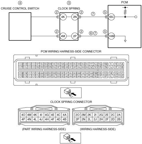
INSPECT CRUISE CONTROL SWITCH CIRCUIT FOR SHORT TO POWER SUPPLY
• Clock spring and PCM connectors are disconnected.
• Switch the ignition to ON (engine off).
• Measure the voltage at the clock spring terminal 2P (wiring harness-side).
• Is there any voltage?
|
Yes
|
Repair or replace the wiring harness for a possible short to power supply, then go to Step 8.
|
|
No
|
Go to the next step.
|
|
7
|
INSPECT CRUISE CONTROL SWITCH CIRCUIT FOR OPEN CIRCUIT
• Clock spring and PCM connectors are disconnected.
• Switch the ignition to off.
• Inspect for continuity between the following terminals (wiring harness-side):
-
― Clock spring terminal 2N—PCM terminal 1BC
― Clock spring terminal 2P—PCM terminal 1AM
• Is there continuity?
|
Yes
|
Go to the next step.
|
|
No
|
Repair or replace the wiring harness for a possible open circuit, then go to the next step.
|
|
8
|
VERIFY DTC TROUBLESHOOTING COMPLETED
• Make sure to reconnect all disconnected connectors.
• Clear the DTC from the PCM memory using the M-MDS.
• Start the engine.
• Perform the KOEO self test.
• Is the same DTC present?
|
Yes
|
Replace the PCM, then go to the next step.
|
|
No
|
Go to the next step.
|
|
9
|
VERIFY AFTER REPAIR PROCEDURE
• Perform the “AFTER REPAIR PROCEDURE”.
• Are any DTCs present?
|
Yes
|
Go to the applicable DTC inspection.
|
|
No
|
DTC troubleshooting completed.
|