DTC P0481:00
Cooling fan relay No.2 and No.3 control circuit malfunction
DETECTION CONDITION
• The PCM monitors the cooling fan relay No.2 and No.3 control signal voltage and current. If the following conditions are met, the PCM determines that there is the cooling fan relay No.2 and No.3 control circuit problem.
-
― The PCM turns the cooling fan relay No.2 and No.3 off, but the voltage of the cooling fan relay No.2 and No.3 control signal remains low for 5 s.― The PCM turns the cooling fan relay No.2 and No.3 on, but the current of the cooling fan relay No.2 and No.3 control signal remains high for 5 s.
Diagnostic support note
• This is a continuous monitor (other).
• The MIL does not illuminate.
• FREEZE FRAME DATA (Mode 2)/Snapshot data is not available.
• The DTC is stored in the PCM memory.
POSSIBLE CAUSE
• Cooling fan relay No.2 and/or No.3 malfunction
• Short to ground or open circuit in cooling fan relay No.2 and/or No.3 power supply circuit
-
― Short to ground in wiring harness between the following terminals:
-
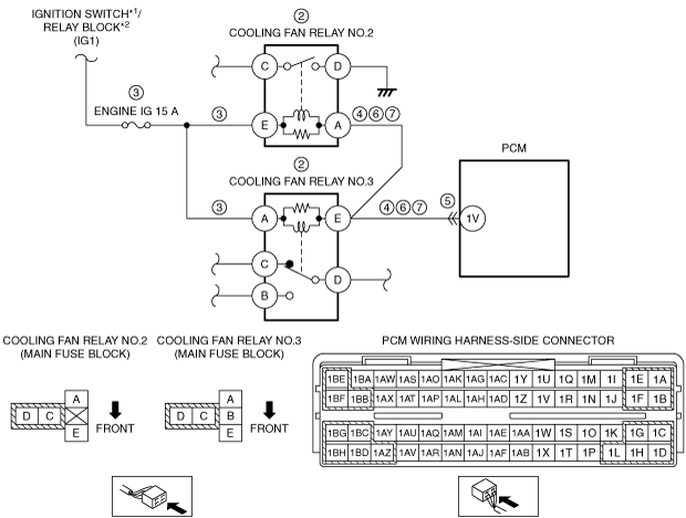
• ENGINE IG 15 A fuse—Cooling fan relay No.2 terminal E• ENGINE IG 15 A fuse—Cooling fan relay No.3 terminal A
― ENGINE IG 15 A fuse malfunction― Open circuit in wiring harness between the following terminals:-
• Ignition switch*1/Relay block*2—Cooling fan relay No.2 terminal E• Ignition switch*1/Relay block*2—Cooling fan relay No.3 terminal A
-
• Short to ground in wiring harness between the following terminals:
-
― Cooling fan relay No.2 terminal A—Cooling fan relay No.3 terminal E― Cooling fan relay No.3 terminal E—PCM terminal 1V
• PCM connector or terminals malfunction
• Short to power supply in wiring harness between the following terminals:
-
― Cooling fan relay No.2 terminal A—Cooling fan relay No.3 terminal E― Cooling fan relay No.3 terminal E—PCM terminal 1V
• Open circuit in wiring harness between the following terminals:
-
― Cooling fan relay No.2 terminal A—Cooling fan relay No.3 terminal E― Cooling fan relay No.3 terminal E—PCM terminal 1V
• PCM malfunction