 |
am6zzw00004530
WATER PUMP REMOVAL/INSTALLATION [MZR-CD 2.2]
id0112f3800700
1. Disconnect the negative battery cable.
2. Remove the engine cover. (See ENGINE COVER REMOVAL/INSTALLATION [MZR-CD 2.2].)
3. Remove the aerodynamic under cover No.2. (See AERODYNAMIC UNDER COVER NO.2 REMOVAL/INSTALLATION.)
4. Drain the engine coolant. (See ENGINE COOLANT REPLACEMENT [MZR-CD 2.2].)
5. Remove the splash shield (RH). (See SPLASH SHIELD REMOVAL/INSTALLATION.)
6. Loosen the water pump pulley bolts before removing the drive belt.
7. Remove the drive belt. (See DRIVE BELT REMOVAL/INSTALLATION [MZR-CD 2.2].)
8. Remove the boost sensor. (See COMMON RAIL REMOVAL/INSTALLATION [MZR-CD 2.2].)
9. Remove the generator. (See GENERATOR REMOVAL/INSTALLATION [MZR-CD 2.2].)
10. Remove the thermostat and thermostat cover. (See THERMOSTAT REMOVAL/INSTALLATION [MZR-CD 2.2].)
11. Disconnect the oil pressure switch connector and A/C compressor connector.
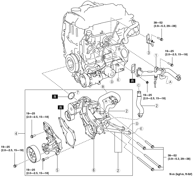
12. Remove in the order indicated in the table.
13. Install in the reverse order of removal.
14. Refill the engine coolant. (See ENGINE COOLANT REPLACEMENT [MZR-CD 2.2].)
15. Inspect for engine coolant leakage. (See ENGINE COOLANT LEAKAGE INSPECTION [MZR-CD 2.2].)
am6zzw00004530
|
|
1
|
Water outlet and upper radiator hose component
|
|
2
|
Water hose
|
|
3
|
Wiring harness bracket
|
|
4
|
Water pump and thermostat case component
|
|
5
|
Water pump
(See Water Pump Installation Note.)
|
|
6
|
Thermostat case
|
|
7
|
O-ring
(See O-ring Installation Note.)
|
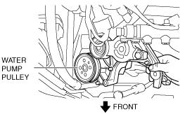
Water Pump And Thermostat Case Component Removal Note
1. Remove the four thermostat case installation bolts.
2. Move the water pump and the thermostat case component inside the engine compartment and remove the water pump pulley.
am6zzw00004393
|
3. Remove the water pump and the thermostat case component.
O-ring Installation Note
1. Apply engine coolant to a new O-ring.
2. Install the O-ring.
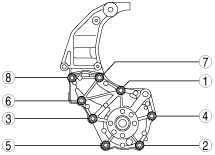
Water Pump Installation Note
1. Tighten the water pump installation bolts in the order shown in the figure.
am6zzw00004394
|
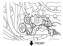
Water Pump And Thermostat Case Component Installation Note
1. Place the water pump and the thermostat case component in the engine compartment.
2. Put the water pump and the thermostat case component in the engine compartment in the position shown in the figure.
am6zzw00004531
|
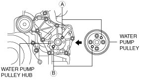
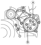
3. Align rotation lock holes A and B on the water pump pulley and on the water pump pulley hub, and temporarily tighten the four water pump pulley bolts.
am6zzw00004396
|
4. Install the thermostat case to the cylinder block and temporarily install the four bolts.
5. Tighten the thermostat case installation bolts in the order shown in the figure.
am6zzw00004397
|
6. Insert a suitable hexagonal bit socket into the rotation lock hole A or B and lock the water pump pulley against rotation.
am6zzw00004398
|
7. Tighten the water pump pulley bolts to the specified tightening torque.
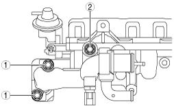
Water Outlet Installation Note
1. Tighten the water outlet installation nuts and bolt in the order shown in the figure.
am6zzw00004399
|