 |
am6zzw00003152
VARIABLE BOOST CONTROL (VBC) SOLENOID VALVE INSPECTION [MZR-CD 2.2]
id0113f3804600
Air Tightness Inspection
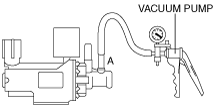
1. Connect a vacuum pump to the VBC solenoid valve port A, and apply vacuum.
am6zzw00003152
|
2. Verify that the vacuum increases to –80 kPa {–600 mmHg, –24 inHg} or more.
Operation Inspection
1. Connect a vacuum pump to the VBC solenoid valve port A, and apply vacuum.
2. Switch the ignition to on.
3. Simulate the VBCV PID to 100% using the M-MDS. (See ON-BOARD DIAGNOSTIC TEST [MZR-CD 2.2].)
4. Verify that the vacuum is decreased.
Resistance Inspection
1. Disconnect the negative battery cable.
2. Disconnect the VBC solenoid valve connector.
3. Measure the resistance between the VBC solenoid valve terminals.
am6zzw00003153
|
