am6zzw00003384
|
FUEL TANK INSPECTION [MZR-CD 2.2]
id0114f2803200
1. Complete the “BEFORE SERVICE PRECAUTION”. (See BEFORE SERVICE PRECAUTION [MZR-CD 2.2].)
2. Disconnect the negative battery cable.
3. Remove the fuel tank. (See FUEL TANK REMOVAL/INSTALLATION [MZR-CD 2.2].)
4. Perform the following procedure to verify the fuel tank airtightness.
am6zzw00003384
|
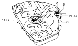
5. Plug the fuel gauge sender unit pipe and port B.
am6zzw00000262
|
6. Level the fuel tank.
7. Apply a pressure of 3 kPa {23 mmHg, 0.9 inHg} to port A and wait for a while.
8. With the pressure still applied, verify that there is airflow from port C and the pressure is 0—3 kPa {0—23 mmHg, 0—0.9 inHg}.
9. Apply a pressure of –0.5 kPa {–3.7 mmHg, –0.1 inHg} to port A and wait for a while.
10. With the pressure still applied, verify that there is airflow from port C and the pressure is –0.5—0 kPa {–3.7—0 mmHg, 0—–0.1 inHg}.
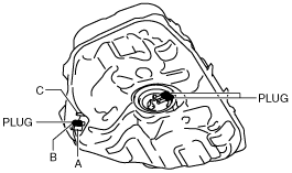
11. Apply a pressure of 3 kPa {23 mmHg, 0.9 inHg} to port A and wait for a while.
am6zzw00000263
|
12. With the pressure still applied, verify that there is no airflow from port C.