 |
am6zzw00005705
SUPPLY PUMP REMOVAL/INSTALLATION [MZR-CD 2.2]
id0114f2805700
|
STEP |
ACTION |
PAGE/CONDITION |
|---|---|---|
|
1
|
Replace the supply pump.
|
–
|
|
2
|
Switch the ignition to on.
|
–
|
|
3
|
Perform supply pump data reset procedure.
|
|
|
4
|
Start the engine.
|
Verify that the MIL dose not illuminate.
|
|
5
|
Switch the ignition to off (Engine off).
|
–
|
|
6
|
Perform KOEO self-test procedure.
|
|
|
7
|
Switch the ignition to off.
|
–
|
|
8
|
Wait for 20 s.
|
–
|
|
9
|
Start the engine.
|
–
|
|
10
|
Perform KOER self-test procedure.
|
Warm up until the exhaust gas temperature (EXHTEMP1, EXHTEMP2 PID) is 100 °C {212 °F} or more.
|
|
11
|
Switch the ignition to off.
|
–
|
1. Disconnect the negative battery cable. (See BATTERY REMOVAL/INSTALLATION [MZR-CD 2.2].)
2. Remove the engine cover. (See BEFORE SERVICE PRECAUTION [MZR-CD 2.2].)
3. Remove the battery and battery tray. (See BATTERY REMOVAL/INSTALLATION [MZR-CD 2.2].)
4. Remove the air inlet hose No.1, air inlet hose No.2 and air inlet pipe as single unit. (See INTAKE-AIR SYSTEM REMOVAL/INSTALLATION [MZR-CD 2.2].)
5. Complete the “BEFORE SERVICE PRECAUTION”. (See BEFORE SERVICE PRECAUTION [MZR-CD 2.2].)
6. Remove in the order indicated in the table.
7. Install in the reverse order of removal.
8. Complete the “AFTER SERVICE PRECAUTION”. (See AFTER SERVICE PRECAUTION [MZR-CD 2.2].)
am6zzw00005705
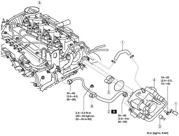
|
|
1
|
Fuel hose
(See Fuel Hose Installation Note.)
|
|
2
|
Injection pipe (supply pump side)
|
|
3
|
Suction control valve connector
|
|
4
|
Supply pump
|
|
5
|
Spacer
|
Supply Pump Installation Note
1. Visually inspect the O-ring.
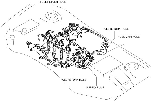
Fuel Hose Installation Note
1. Install the fuel main hose and fuel return hose as shown in the figure.
L.H.D.
am6zzw00004266
|
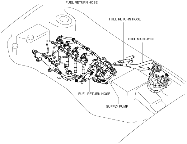
R.H.D.
am6zzw00004267
|
2. Fit the fuel pipe onto the respective fittings, and install clamps as shown.
am6zzw00004268
|