am6zzw00005442
|

am6zzw00005443
|
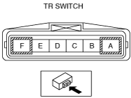
TRANSAXLE RANGE (TR) SWITCH INSTALLATION [FS5A-EL]
id051721803800
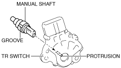
1. Install the TR switch to the manual shaft.
am6zzw00005442
|
am6zzw00005443
|
am6zzw00005444
|
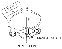
2. Adjust the TR switch.
am6zzw00004873
|
am6zzw00005443
|
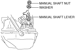
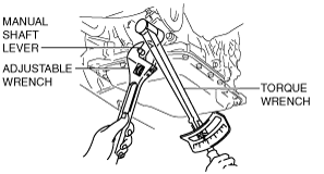
3. Install the manual shaft nut and washer, manual shaft lever.
am6zzw00005445
|
4. Set the adjustable wrench as shown to hold the manual shaft lever, and tighten the manual shaft nut.
am6zzw00004874
|
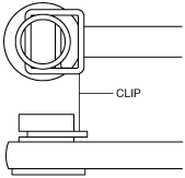
5. Install the clip to the selector cable as shown in the figure.
am6zzw00005446
|
6. Select the selector lever to N position.
7. Connect the selector cable to the manual shaft lever.
am6zzw00005447
|
8. Connect the TR switch connector.
9. Install the air cleaner component. (See INTAKE-AIR SYSTEM REMOVAL/INSTALLATION [MZR 1.8, MZR 2.0, MZR 2.5].) (See INTAKE-AIR SYSTEM REMOVAL/INSTALLATION [MZR 2.0 DISI].)
10. Connect the negative battery cable.