|
am6zzw00005683
INTAKE-AIR SYSTEM REMOVAL/INSTALLATION [MZR 2.0 DISI]
id0113d4801900
1. Disconnect the negative battery cable. (See BATTERY REMOVAL/INSTALLATION [MZR 2.0 DISI].)
2. Remove the plug hole plate. (See PLUG HOLE PLATE REMOVAL/INSTALLATION [MZR 2.0 DISI].)
3. Disconnect the wiring harness.
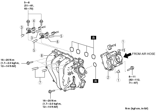
4. Remove in the order indicated in the table.
5. Install in the reverse order of removal.
Step 1
am6zzw00005683
|
|
1
|
Air cleaner cover
|
|
2
|
Air cleaner element
|
|
3
|
Air cleaner case
|
|
4
|
Fresh-air duct
|
|
5
|
Resonance chamber
|
|
6
|
MAF/IAT sensor
|
|
7
|
Ventilation hose (air hose side)
|
|
8
|
Resonance chamber
|
|
9
|
Air hose
(See Air Hose Removal Note.)
|
|
9
|
Air cleaner bracket
|
Step 2
am3zzw00007747
|
|
1
|
Water hose
(SeeWater Hose Removal Note.)
|
|
2
|
Throttle body
|
|
3
|
Vacuum hose
|
|
4
|
Variable swirl solenoid valve
|
|
5
|
Vacuum hose
|
|
6
|
Variable intake air solenoid valve
|
|
7
|
Vacuum hose
|
|
8
|
Intake manifold
(See Intake Manifold Removal Note.)
|
Resonance Chamber Removal Note
1. Remove the front mudguard (LH). (See FRONT MUDGUARD REMOVAL/INSTALLATION.)
2. Remove the resonance chamber.
Air Hose Removal Note
1. Remove the purge solenoid valve bracket. (See PURGE SOLENOID VALVE REMOVAL/INSTALLATION [MZR 2.0 DISI].)
Water Hose Removal Note
1. Drain the engine coolant. (See ENGINE COOLANT REPLACEMENT [MZR 2.0 DISI].)
2. Disconnect the water hose.
Intake Manifold Removal Note
1. Remove the aerodynamic under cover No.2. (See AERODYNAMIC UNDER COVER NO.2 REMOVAL/INSTALLATION.)
2. Remove the battery and battery tray. (See BATTERY REMOVAL/INSTALLATION [MZR 2.0 DISI].)
3. Remove the EGR pipe. (See EGR PIPE REMOVAL/INSTALLATION [MZR 2.0 DISI].)
4. Remove the coolant reserve tank. (See COOLANT RESERVE TANK REMOVAL/INSTALLATION [MZR 2.0 DISI].)
5. Remove all clips for securing wiring harnesses from the intake manifold.
6. Disconnect the vacuum hoses connecting the intake manifold.
7. Remove the intake manifold.
Ventilation Hose (Air Hose Side) Installation Note
1. Connect the ventilation hose (air hose side).
2. Verify that the ventilation hose connection area is inserted completely.
Air Cleaner Case Installation Note
1. Verify that the rubber mounts are set in the air cleaner bracket (3 locations).
2. Install the projections on the frame side (2 locations).
3. Verify that the projections on the frame side are installed securely.
4. Install the projection on the engine side (remaining location).
5. Verify that the projection on the engine side installed securely.