 |
am6zzw00001179
DTC C200B:1C/C200B:1E
id060200817000
|
DTC
|
C200B:1C/C200B:1E
|
Torque sensor
|
|
|
DETECTION CONDITION
|
• Open or short circuit is detected in torque sensor circuit
|
||
|
POSSIBLE CAUSE
|
• Open or short to ground circuit in wiring harness between the following EPS control module terminals and torque sensor terminals.
• Torque sensor malfunction
• EPS control module malfunction
• Poor connection at connectors
|
||
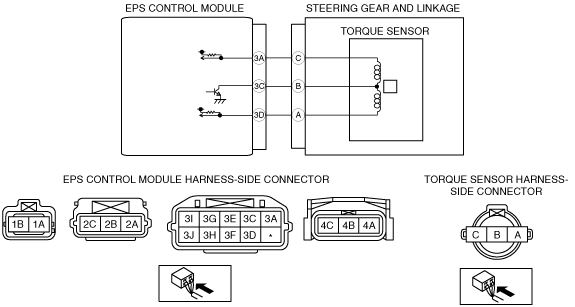
System wiring diagram
am6zzw00001179
|
Diagnostic Procedure
|
Step |
Inspection |
Action |
|
|---|---|---|---|
|
1
|
INSPECT TORQUE SENSOR USING M-MDS
• Connect the M-MDS to the DLC-2.
• Switch the ignition to ON (engine OFF).
• Access “SS_TRQ1” and “SS_TRQ2” PIDs.
• Verify that the data monitor value changes when the steering wheel is turned.
• Do the torque sensor signal values change in the same way?
|
Yes
|
Malfunction may be temporary. Go to step 6.
|
|
No
|
Go to the next step.
|
||
|
2
|
INSPECT WHETHER MALFUNCTION IS CAUSED BY POOR CONNECTION OF EPS CM OR PIN DEFORMATION
• Switch the ignition to off.
• Inspect connection of the EPS control module and wiring harness.
• Disconnect the EPS control module connector.
• Inspect whether malfunction is caused by bent or poorly connected EPS control module connector pin.
• Are the connector connection, connector pins, and wiring harness normal?
|
Yes
|
Go to the next step.
|
|
No
|
Repair or replace the faulty connector wiring harness, then go to Step 6.
|
||
|
3
|
IINSPECT TORQUE SENSOR CIRCUIT FOR OPEN CIRCUIT
• Inspect for continuity between the EPS control module terminals and torque sensor terminals.
• Is there continuity?
|
Yes
|
Go to the next step.
|
|
No
|
Repair or replace the wiring harness for open circuit between the EPS control module and torque sensor, then go to Step 6.
|
||
|
4
|
INSPECT TORQUE SENSOR CIRCUIT FOR SHORT TO POWER
• Measure the voltage between the torque sensor terminals and ground.
• Is there any B+?
|
Yes
|
Repair or replace the wiring harness for short to power between the EPS control module and torque sensor, then go to Step 6.
|
|
No
|
Go to the next step.
|
||
|
5
|
INSPECT TORQUE SENSOR CIRCUIT FOR SHORT TO GROUND
• Inspect for continuity between the torque sensor terminals and ground.
• Is there continuity?
|
Yes
|
Repair or replace the wiring harness for short to ground between the EPS control module and torque sensor, then go to the next step.
|
|
No
|
Replace the steering gear and linkage (torque sensor), then go to the next step.
|
||
|
6
|
VERIFY THAT SAME DTC IS NOT PRESENT
• Make sure to reconnect all disconnected connectors.
• Clear the DTC from the memory.
• Is the same DTC present?
|
Yes
|
Repeat the inspection from Step 1.
If the malfunction recurs, replace the EPS control module.
|
|
No
|
Go to the next step.
|
||
|
7
|
VERIFY THAT NO OTHER DTCs ARE PRESENT
• Are any other DTCs output?
|
Yes
|
Go to the applicable DTC inspection.
|
|
No
|
DTC troubleshooting completed.
|
||