 |
am6zzw00006156
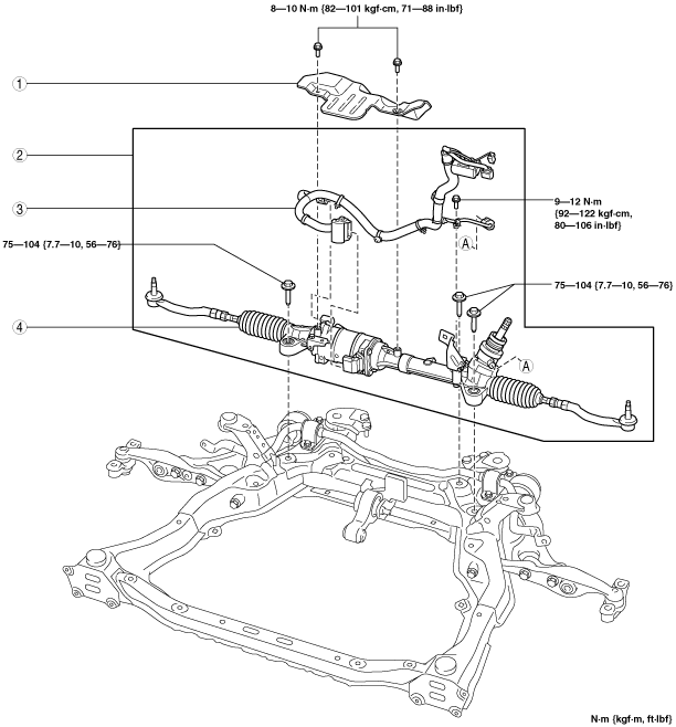
STEERING GEAR AND LINKAGE REMOVAL/INSTALLATION [L.H.D.]
id0613008017a1
1. Remove the steering shaft cover and disconnect the steering shaft from the steering gear and linkage, and then remove the steering dust cover. (See STEERING WHEEL AND COLUMN REMOVAL/INSTALLATION [WITHOUT ADVANCED KEYLESS ENTRY AND PUSH BUTTON START SYSTEM].) (See STEERING WHEEL AND COLUMN REMOVAL/INSTALLATION [WITH ADVANCED KEYLESS ENTRY AND PUSH BUTTON START SYSTEM].)
2. Remove the aerodynamic under cover No. 1 and No. 2. (See AERODYNAMIC UNDER COVER NO.1 REMOVAL/INSTALLATION.) (See AERODYNAMIC UNDER COVER NO.2 REMOVAL/INSTALLATION.)
3. Remove the front auto leveling sensor. (Vehicle with discharge headlight system) (See AUTO LEVELING SENSOR REMOVAL/INSTALLATION.)
4. Remove the transverse member. (See TRANSVERSE MEMBER REMOVAL/INSTALLATION.)
5. Remove the front crossmember component. (See FRONT CROSSMEMBER REMOVAL/INSTALLATION.)
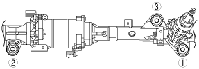
6. Remove in the order indicated in the table.
7. Install in the reverse order of removal.
8. After installation, inspect the front wheel alignment and adjust it if necessary. (See FRONT WHEEL ALIGNMENT [European (L.H.D., U.K.) Specs.].) (See FRONT WHEEL ALIGNMENT [Australian Specs. and General (L.H.D., R.H.D.) Specs.].)
9. Set the EPS system to the neutral position. (See EPS SYSTEM NEUTRAL POSITION SETTING.)
am6zzw00006156
|
|
1
|
Insulator
|
|
2
|
Steering gear and linkage component
|
|
3
|
Wiring harness
|
|
4
|
Steering gear and linkage
|
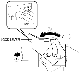
Wiring Harness Removal Note
1. Remove the EPS motor connector using the following procedure as shown in the figure.
am6zzw00002183
|
2. Remove the torque sensor connector and resolver sensor connector.
3. Remove the bolts and clips, then remove the wiring harness from the steering gear.
Steering Gear and Linkage Installation Note
1. Temporarily tighten the bolts.
2. Tighten the steering gear and linkage installation bolts to the specified torque in the order shown in the figure.
am6zzw00001725
|
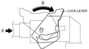
Wiring Harness Installation Note
1. Install the EPS motor connector using the following procedure as shown in the figure.
am6zzw00002182
|
2. Install the wiring harness connectors to the torque sensor and resolver sensor.
3. Install the clips of the wiring harness.
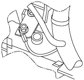
4. Route the wiring harness below the resolver sensor and tighten the wiring harness to the specified torque with its crimped area facing up and its end contacting the bracket’s lock against rotation.
am6zzw00001965
|