 |
am6zzw00006712
DTC U0028:88
id080200847600
System Malfunction Location
|
DTC |
System Malfunction Location |
|---|---|
|
M-MDS display |
|
|
U0028:88
|
DSC HU/CM communication fault
|
Detection Condition
Possible Causes
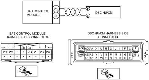
System Wiring Diagram
am6zzw00006712
|
Diagnostic Procedure
|
STEP |
INSPECTION |
ACTION |
|
|---|---|---|---|
|
1
|
INSPECT DSC HU/CM CONNECTOR
• Switch the ignition to off.
• Disconnect the negative battery cable and wait for 1 min or more.
• Disconnect the DSC HU/CM connector.
• Inspect the DSC HU/CM connector terminals for poor connection (such as damaged/pulled-out pins, and corrosion).
• Is there any malfunction?
|
Yes
|
Repair or replace the terminal, then go to Step 5.
|
|
No
|
Go to the next step.
|
||
|
2
|
INSPECT SAS CONTROL MODULE CONNECTOR
• Disconnect the SAS control module connectors. (See SAS CONTROL MODULE REMOVAL/INSTALLATION.)
• Inspect the SAS control module connector terminal for poor connection (such as damaged/pulled-out pins, and corrosion).
• Is there any malfunction?
|
Yes
|
Repair or replace the terminal, then go to Step 5.
|
|
No
|
Go to the next step.
|
||
|
3
|
INSPECT WIRING HARNESS BETWEEN DSC HU/CM AND SAS CONTROL MODULE
• Inspect the wiring harness between SAS control module terminal 2K and DSC HU/CM terminal F, SAS control module terminal 2I and DSC HU/CM terminal G for the following:
• Is the wiring harness normal?
|
Yes
|
Go to the next step.
|
|
No
|
Replace the wiring harness between the SAS control module and the DSC HU/CM.
|
||
|
4
|
INSPECT THE WIRING HARNESS BETWEEN THE SAS CONTROL MODULE AND DSC HU/CM FOR A SHORT CIRCUIT TO THE POWER SUPPLY
• Connect the negative battery cable.
• Switch the ignition to ON with SAS control module and DSC HU/CM connector disconnected.
• Measure the voltage of SAS control module connector terminals 2K and 2I of SAS control module harness side connector.
• Is the voltage measured?
|
Yes
|
Repair or replace the wiring harness for a possible short to power supply, then go to the next step.
|
|
No
|
Replace the DSC HU/CM, then go to the next step.
|
||
|
5
|
VERIFY TROUBLESHOOTING COMPLETED
• Make sure to reconnect all disconnected connectors.
• Clear the DTC from the SAS control module memory using the M-MDS.
• Switch the ignition to off then switch the ignition to ON.
• Is the same DTC present?
|
Yes
|
Replace the SAS control module.
|
|
No
|
DTC troubleshooting completed.
|
||