 |
am6zzw00006031
DTC U0028:87 [REAR VEHICLE MONITORING SYSTEM]
id0902z2886700
|
DESCRIPTION |
Communication error between rear vehicle monitoring control module (RH) and (LH) |
|---|---|
|
DETECTION CONDITION
|
• Communication error between rear vehicle monitoring control module (RH) and (LH).
|
|
POSSIBLE CAUSE
|
• Rear vehicle monitoring control module (LH)/(RH) connector or terminals malfunction
• Short to ground in wiring harness between the following terminals:
• Short to power supply in wiring harness between the following terminals:
• Rear vehicle monitoring control module circuits are shorted to each other.
• Open circuit in wiring harness between the following terminals:
• Rear vehicle monitoring control module (LH) malfunction
• Rear vehicle monitoring control module (RH) malfunction
|
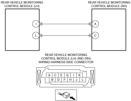
System Wiring Diagram
am6zzw00006031
|
Diagnostic Procedure
|
STEP |
INSPECTION |
ACTION |
|
|---|---|---|---|
|
1
|
INSPECT REAR VEHICLE MONITORING CONTROL MODULE (LH) AND (RH) CONNECTORS AND TERMINALS
• Switch the ignition to off.
• Disconnect the negative battery cable.
• Disconnect the rear vehicle monitoring control module (LH) and (RH) connectors.
• Inspect the connectors and terminals (corrosion, damage, pin disconnection).
• Is there any malfunction?
|
Yes
|
Repair or replace the connector or terminals, then go to Step 7.
|
|
No
|
Go to the next step.
|
||
|
2
|
INSPECT CAN BUS CIRCUIT FOR SHORT TO GROUND
• Rear vehicle monitoring control module (LH) and (RH) connectors are disconnected.
• Inspect for continuity between the following terminals (wiring harness-side) and body ground:
• Is there continuity?
|
Yes
|
Repair or replace the wiring harness for a possible short to ground, then go to Step 7.
|
|
No
|
Go to the next step.
|
||
|
3
|
INSPECT CAN BUS CIRCUIT FOR SHORT TO POWER SUPPLY
• Rear vehicle monitoring control module (LH) and (RH) connectors are disconnected.
• Reconnect the negative battery cable.
• Switch the ignition to ON.
• Measure the voltage at the following terminals (wiring harness-side):
• Is there any voltage?
|
Yes
|
Repair or replace the wiring harness for a possible short to power supply, then go to Step 7.
|
|
No
|
Go to the next step.
|
||
|
4
|
INSPECT CAN BUS CIRCUIT FOR SHORT TO EACH OTHER
• Rear vehicle monitoring control module (LH) and (RH) connectors are disconnected.
• Switch the ignition to off.
• Disconnect the negative battery cable.
• Inspect for continuity between rear vehicle monitoring control module (LH) terminal I and L (wiring harness-side).
• Is there continuity?
|
Yes
|
Repair or replace the wiring harness for a possible short to each other, then go to Step 7.
|
|
No
|
Go to the next step.
|
||
|
5
|
INSPECT CAN BUS CIRCUIT FOR OPEN CIRCUIT
• Rear vehicle monitoring control module (LH) and (RH) connectors are disconnected.
• Inspect for continuity between the following terminals (wiring harness-side):
• Is there continuity?
|
Yes
|
Go to the next step.
|
|
No
|
Repair or replace the wiring harness for a possible open circuit, then go to Step 7.
|
||
|
6
|
VERIFY REAR VEHICLE MONITORING CONTROL MODULE (LH) MALFUNCTION
• Make sure to reconnect all disconnected connectors.
• Reconnect the negative battery cable.
• Clear the DTC from the rear vehicle monitoring control module using the M-MDS.
• Verify the rear vehicle monitoring system DTC using the M-MDS.
• Is the same DTC present?
|
Yes
|
Replace the rear vehicle monitoring control module (LH), then go to the next step.
|
|
No
|
Go to Step 8.
|
||
|
7
|
VERIFY TROUBLESHOOTING COMPLETED
• Make sure to reconnect all disconnected connectors.
• Reconnect the negative battery cable.
• Clear the DTC from the rear vehicle monitoring control module using the M-MDS.
• Verify the rear vehicle monitoring system DTC using the M-MDS.
• Is the same DTC present?
|
Yes
|
Replace the rear vehicle monitoring control module (RH), then go to the next step.
|
|
No
|
Go to the next step.
|
||
|
8
|
VERIFY THAT NO OTHER DTCs ARE PRESENT
• Are any DTCs present?
|
Yes
|
Go to the applicable DTC inspection.
|
|
No
|
DTC troubleshooting completed.
|
||