|
1
|
RECORD VEHICLE STATUS WHEN DTC WAS DETECTED TO UTILIZE WITH REPEATABILITY VERIFICATION
-
Note
-
• Recording can be facilitated using the screen capture function of the PC.
• Record the freeze frame data/snap shot data.
|
—
|
Go to the next step.
|
|
2
|
VERIFY OTHER RELATED DTCs
• Switch the ignition OFF, and then switch it ON (engine off).
• Display the DTCs using the M-MDS.
• Has any DTC other than P0652:00 been stored?
|
Yes
|
Repair the malfunctioning location according to the applicable DTC troubleshooting.
|
|
No
|
Go to the next step.
|
|
3
|
INSPECT APP SENSOR CONNECTOR CONDITION
• Switch the ignition OFF.
• Disconnect the APP sensor connector
• Inspect the connector engagement and connection condition, and inspect the terminals for damage, deformation, corrosion, or disconnection.
• Is the connector normal?
|
Yes
|
Go to the next step.
|
|
No
|
Repair or replace the connector, then go to Step 15.
|
|
4
|
INSPECT CMP SENSOR CONNECTOR CONDITION
• Disconnect the CMP sensor connector.
• Inspect the connector engagement and connection condition, and inspect the terminals for damage, deformation, corrosion, or disconnection.
• Is the connector normal?
|
Yes
|
Go to the next step.
|
|
No
|
Repair or replace the connector, then go to Step 15.
|
|
5
|
INSPECT EGR VALVE/EGR VALVE POSITION SENSOR CONNECTOR CONDITION
• Disconnect the EGR valve/EGR valve position sensor connectors.
• Inspect the connector engagement and connection condition, and inspect the terminals for damage, deformation, corrosion, or disconnection.
• Is the connector normal?
|
Yes
|
Go to the next step.
|
|
No
|
Repair or replace the connector, then go to Step 15.
|
|
6
|
INSPECT INTAKE SHUTTER VALVE/INTAKE SHUTTER VALVE POSITION SENSOR CONNECTOR CONDITION
• Disconnect the intake shutter valve/intake shutter valve position sensor connectors.
• Inspect the connector engagement and connection condition, and inspect the terminals for damage, deformation, corrosion, or disconnection.
• Is the connector normal?
|
Yes
|
Go to the next step.
|
|
No
|
Repair or replace the connector, then go to Step 15.
|
|
7
|
INSPECT EXHAUST GAS PRESSURE SENSOR NO.1 CONNECTOR CONDITION
• Disconnect the exhaust gas pressure sensor No.1 connector.
• Inspect the connector engagement and connection condition, and inspect the terminals for damage, deformation, corrosion, or disconnection.
• Is the connector normal?
|
Yes
|
Go to the next step.
|
|
No
|
Repair or replace the connector, then go to Step 15.
|
|
8
|
INSPECT EXHAUST GAS PRESSURE SENSOR NO.2 CONNECTOR CONDITION
• Disconnect the exhaust gas pressure sensor No.2 connector.
• Inspect the connector engagement and connection condition, and inspect the terminals for damage, deformation, corrosion, or disconnection.
• Is the connector normal?
|
Yes
|
Go to the next step.
|
|
No
|
Repair or replace the connector, then go to Step 15.
|
|
9
|
INSPECT MAP SENSOR NO.1 CONNECTOR CONDITION
• Disconnect the MAP sensor No.1 connector.
• Inspect the connector engagement and connection condition, and inspect the terminals for damage, deformation, corrosion, or disconnection.
• Is the connector normal?
|
Yes
|
Go to the next step.
|
|
No
|
Repair or replace the connector, then go to Step 15.
|
|
10
|
INSPECT REGULATING VALVE ACTUATOR/REGULATING VALVE ACTUATOR POSITION SENSOR CONNECTOR CONDITION
• Disconnect the regulating valve actuator/regulating valve actuator position sensor connectors.
• Inspect the connector engagement and connection condition, and inspect the terminals for damage, deformation, corrosion, or disconnection.
• Is the connector normal?
|
Yes
|
Go to the next step.
|
|
No
|
Repair or replace the connector, then go to Step 15.
|
|
11
|
INSPECT COOLANT CONTROL VALVE/COOLANT CONTROL VALVE POSITION SENSOR CONNECTOR CONDITION
• Disconnect the coolant control valve/coolant control valve position sensor connector.
• Inspect the connector engagement and connection condition, and inspect the terminals for damage, deformation, corrosion, or disconnection.
• Is the connector normal?
|
Yes
|
Go to the next step.
|
|
No
|
Repair or replace the connector, then go to Step 15.
|
|
12
|
INSPECT FUEL SENSOR (INTEGRATED WITH FUEL INJECTOR NO.2, NO.3) CONNECTOR CONDITION
• Disconnect the fuel sensor (integrated with fuel injector No.2, 3) connector.
• Inspect the connector engagement and connection condition, and inspect the terminals for damage, deformation, corrosion, or disconnection.
• Is the connector normal?
|
Yes
|
Go to the next step.
|
|
No
|
Repair or replace the connector, then go to Step 15.
|
|
13
|
INSPECT PCM CONNECTOR CONDITION
• Disconnect the PCM connector.
• Inspect the connector engagement and connection condition, and inspect the terminals for damage, deformation, corrosion, or disconnection.
• Is the connector normal?
|
Yes
|
Go to the next step.
|
|
No
|
Repair or replace the connector, then go to the next step.
|
|
14
|
INSPECT EACH POWER SUPPLY CIRCUIT FOR SHORT TO GROUND
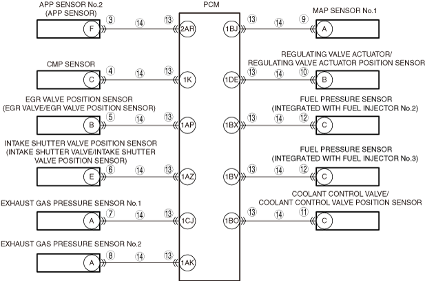
• Verify that the connectors of the APP sensor, sensor, CMP sensor, EGR valve/EGR valve position sensor, intake shutter valve/intake shutter valve position sensor, exhaust gas pressure sensor No.1, exhaust gas pressure sensor No.2, MAP sensor No.1, regulating valve actuator/regulating valve actuator position sensor, coolant control valve/engine control valve position sensor, or the fuel pressure sensor (integrated with fuel injector No.2, 3) are disconnected
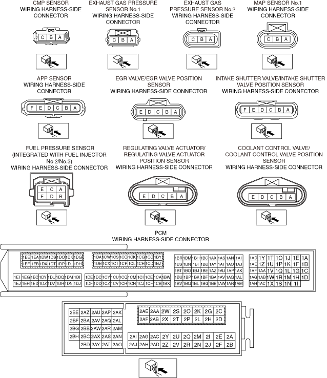
• Inspect for continuity between the following terminals (vehicle wiring harness side) and ground.
-
― APP sensor terminal F
― CMP sensor terminal C
― EGR valve/EGR valve position sensor terminal B
― The intake shutter valve/intake shutter valve position sensor terminal E.
― Exhaust gas pressure sensor No.1 terminal A
― Exhaust gas pressure sensor No.2 terminal A
― MAP sensor No.1 terminal A
― Regulating valve actuator/regulating valve actuator position sensor terminal B
― Coolant control valve/coolant control valve position sensor terminal C
― Fuel pressure sensor (integrated with fuel injector No.2) terminal C
― Fuel pressure sensor (integrated with fuel injector No.3) terminal C
• Is there continuity?
|
Yes
|
Refer to the wiring diagram and verify if there is a common connector between the following terminals.
• APP sensor terminal F and PCM terminal 2AR
• CMP sensor terminal C and PCM terminal 1K
• EGR valve/EGR valve position sensor terminal B and PCM terminal 1AP
• Intake shutter valve/intake shutter valve position sensor terminal E and PCM terminal 1AZ
• Exhaust gas pressure sensor No.1 terminal A and PCM terminal 1CJ
• Exhaust gas pressure sensor No.2 terminal A and PCM terminal 1AK
• MAP sensor No.1 terminal A and PCM terminal 1BJ
• Regulating valve actuator/regulating valve actuator position sensor terminal B and PCM terminal 1DE
• Coolant control valve/coolant control valve position sensor terminal C and PCM terminal 1BO
• Fuel pressure sensor (integrated with fuel injector No.2) terminal C and PCM terminal 1BX
• Fuel pressure sensor (integrated with fuel injector No.3) terminal C and PCM terminal 1BV
If there is a common connector:
• Inspect the common connector and terminals for corrosion, damage, or disconnection and the common wiring harnesses for short to ground to determine the malfunctioning location.
• Repair or replace the malfunctioning location.
If there is no common connector:
• Repair or replace the wiring harness which is shorted to ground.
Go to the next step.
|
|
No
|
Go to the next step.
|
|
15
|
VERIFY THAT REPAIRS HAVE BEEN COMPLETED
• Reconnect all the disconnected connectors.
• Refer to the [MEMORY CLEARING PROCEDURE] and clear the DTC.
• Switch the ignition ON (engine off) and wait for 30 s.
• Display the DTCs using the M-MDS.
• Has DTC P0652:00 been recorded?
|
Yes
|
Repeat the inspection from Step 1.
• If the malfunction recurs, replace the PCM, then go to the next step.
|
|
No
|
Go to the next step.
|
|
16
|
VERIFY OTHER DTCs
• Has any other DTC or pending code been stored?
|
Yes
|
Repair the malfunctioning location according to the applicable DTC troubleshooting.
|
|
No
|
DTC troubleshooting completed.
|