|
1
|
RECORD VEHICLE STATUS WHEN DTC WAS DETECTED TO UTILIZE WITH REPEATABILITY VERIFICATION
-
Note
-
• Recording can be facilitated using the screen capture function of the PC.
• Record the freeze frame data/snap shot data.
|
—
|
Go to the next step.
|
|
2
|
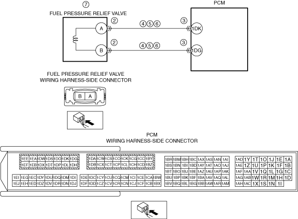
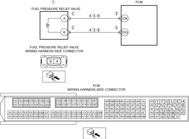
INSPECT FUEL PRESSURE RELIEF VALVE CONNECTOR CONDITION
• Switch the ignition OFF.
• Disconnect the fuel pressure relief valve connector.
• Inspect the connector engagement and connection condition, and inspect the terminals for damage, deformation, corrosion, or disconnection.
• Is the connector normal?
|
Yes
|
Go to the next step.
|
|
No
|
Repair or replace the connector, then go to Step 8.
|
|
3
|
INSPECT PCM CONNECTOR CONDITION
• Disconnect the PCM connector.
• Inspect the connector engagement and connection condition, and inspect the terminals for damage, deformation, corrosion, or disconnection.
• Is the connector normal?
|
Yes
|
Go to the next step.
|
|
No
|
Repair or replace the connector, then go to Step 8.
|
|
4
|
INSPECT FUEL PRESSURE RELIEF VALVE CONTROL CIRCUIT FOR SHORT TO GROUND
• Verify that the fuel pressure relief valve connector is disconnected.
• Inspect for continuity between the following terminals (vehicle wiring harness side) and ground.
-
― Fuel pressure relief valve terminal A
― Fuel pressure relief valve terminal B
• Is there continuity?
|
Yes
|
Refer to the wiring diagram and verify if there is a common connector between the following terminals.
• Fuel pressure relief valve terminal A and PCM terminal 1DK
• Fuel pressure relief valve terminal B and PCM terminal 1DG
If there is a common connector:
-
― Inspect the common connector and terminals for corrosion, damage, or disconnection and the common wiring harnesses for short to ground to determine the malfunctioning location.
― Repair or replace the malfunctioning location.
If there is no common connector:
-
― Repair or replace the wiring harness which is shorted to ground.
Go to Step 8.
|
|
No
|
Go to the next step.
|
|
5
|
INSPECT FUEL PRESSURE RELIEF VALVE CONTROL CIRCUIT FOR SHORT TO POWER SUPPLY
• Verify that the fuel pressure relief valve connector and the PCM connector are disconnected.
• Switch the ignition ON (engine off).
• Measure the voltage at the following terminals (vehicle wiring harness side).
-
― Fuel pressure relief valve terminal A
― Fuel pressure relief valve terminal B
• Is the voltage 0 V?
|
Yes
|
Go to the next step.
|
|
No
|
Refer to the wiring diagram and verify if there is a common connector between the following terminals.
• Fuel pressure relief valve terminal A and PCM terminal 1DK
• Fuel pressure relief valve terminal B and PCM terminal 1DG
If there is a common connector:
-
― Inspect the common connector and terminals for corrosion, damage, or disconnection and the common wiring harnesses for short to power supply to determine the malfunctioning location.
― Repair or replace the malfunctioning location.
If there is no common connector:
-
― Repair or replace the wiring harness which is shorted to the power supply.
Go to Step 8.
|
|
6
|
INSPECT FUEL PRESSURE RELIEF VALVE CONTROL CIRCUIT FOR OPEN CIRCUIT
• Verify that the fuel pressure relief valve connector and the PCM connector are disconnected.
• Inspect between the following terminals (vehicle wiring harness side) for continuity.
-
― Fuel pressure relief valve terminal A and PCM terminal 1DK
― Fuel pressure relief valve terminal B and PCM terminal 1DG
• Is there continuity?
|
Yes
|
Go to the next step.
|
|
No
|
Refer to the wiring diagram and verify if there is a common connector between the following terminals.
• Fuel pressure relief valve terminal A and PCM terminal 1DK
• Fuel pressure relief valve terminal B and PCM terminal 1DG
If there is a common connector:
-
― Inspect the common connector and terminals for corrosion, damage, or disconnection and the common wiring harnesses for an open circuit to determine the malfunctioning location.
― Repair or replace the malfunctioning location.
If there is no common connector:
-
― Repair or replace the wiring harness which has an open circuit.
Go to Step 8.
|
|
7
|
INSPECT FUEL PRESSURE RELIEF VALVE
• Inspect the fuel pressure relief valve.
• Is the fuel pressure relief valve normal?
|
Yes
|
Go to the next step.
|
|
No
|
Replace the common rail, then go to the next step.
|
|
8
|
VERIFY THAT REPAIRS HAVE BEEN COMPLETED
• Reconnect all disconnected connectors and hoses.
• Refer to the [MEMORY CLEARING PROCEDURE] and clear the DTC.
• Start the engine and warm it up.
• Stop all electrical loads. (Such as A/C, headlights, blower fan, rear window defroster)
• Drive the vehicle on flat roads under the following conditions 4 times repeatedly.
-
Warning
-
• Observe legal speed limits when driving the vehicle and perform the procedure in a location where safety can be assured.
-
1. Accelerate to 15 km/h and decelerate to 0 km/h.
2. Wait for 20 s while idling.
3. Accelerate to 30 km/h, and decelerate to 0 km/h after driving the vehicle while maintaining the speed for 20 s.
4. Wait for 20 s while idling.
5. Accelerate to 50 km/h, and decelerate to 0 km/h after driving the vehicle while maintaining the speed for 20 s.
6. Wait for 20 s while idling.
• Accelerate to 70 km/h and drive the vehicle while maintaining the speed for 60 s.
• Decelerate to 50 km/h and drive the vehicle while maintaining the speed for 60 s.
• Accelerate to 70 km/h and drive the vehicle while maintaining the speed for 60 s.
• Accelerate to 100 km/h and drive the vehicle while maintaining the speed for 30 s.
• Accelerate to 120 km/h and decelerate to 0 km/h.
• Stop the engine.
• Display the DTCs using the M-MDS.
• Has DTC P009B:00 been recorded?
|
Yes
|
Repeat the inspection from Step 1.
• If the malfunction recurs, replace the PCM, then go to the next step.
|
|
No
|
Go to the next step.
|
|
9
|
VERIFY OTHER DTCs
• Has any other DTC or pending code been stored?
|
Yes
|
Repair the malfunctioning location according to the applicable DTC troubleshooting.
|
|
No
|
DTC troubleshooting completed.
|