 |
am6zzw00014422
DTC P058A:00 [PCM (SKYACTIV-D 2.2)]
id0102j5401100
Engine Type
|
Item |
Reference |
|---|---|
|
Without SCR System
|
(See Without SCR System.)
|
|
With SCR System
|
(See With SCR System.)
|
Without SCR System
Details On DTCs
|
DESCRIPTION |
Current sensor: Function malfunction |
|
|---|---|---|
|
DETECTION CONDITION
|
Determination conditions
|
• Error signal from the current sensor is received.
|
|
Preconditions
|
• Not applicable
|
|
|
Malfunction determination period
|
• 5 s period
|
|
|
Drive cycle
|
• 1
|
|
|
Self test type
|
• CMDTC self test
|
|
|
Sensor used
|
• Current sensor
|
|
|
FAIL-SAFE FUNCTION
|
• Inhibits engine-stop by operating the i-stop function.
|
|
|
VEHICLE STATUS WHEN DTCs ARE OUTPUT
|
• Flashes i-stop warning light (amber).
• Illuminates master warning light
• A warning message is displayed on the center display. (With center display)
• A warning message is displayed on the LCD in the instrument cluster. (Type A instrument cluster)
• Illuminates charging system warning light.
• The engine cannot be started or the engine may stall due to battery voltage decrease.
|
|
|
POSSIBLE CAUSE
|
• Connector or terminal malfunction of the following parts:
• Short to ground or open circuit in current sensor power supply circuit
• Short to ground in wiring harness between the following terminals:
• Short to power supply in wiring harness between the following terminals:
• Open circuit in wiring harness between the following terminals:
• Current sensor malfunction
• Front body control module (FBCM) malfunction
• PCM malfunction
|
|
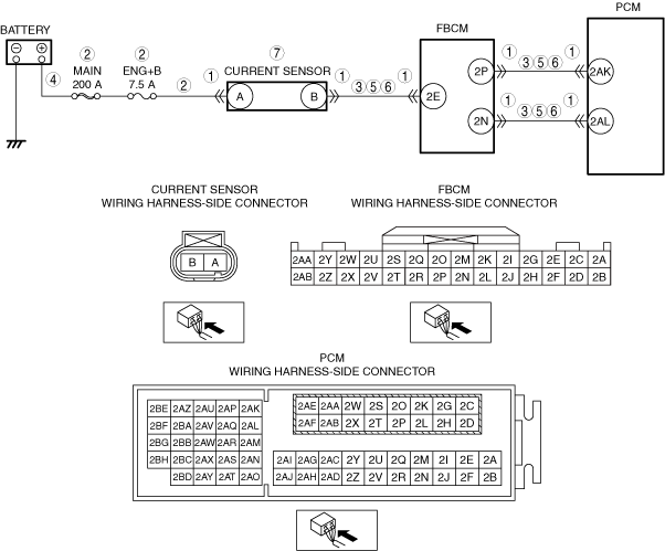
System Wiring Diagram
am6zzw00014422
|
Function Explanation (DTC Detection Outline)
Repeatability Verification Procedure
PID Item/Simulation Item Used In Diagnosis
Function Inspection Using M-MDS
|
STEP |
INSPECTION |
RESULTS |
ACTION |
|---|---|---|---|
|
1
|
PURPOSE: VERIFY RELATED SERVICE INFORMATION AVAILABILITY
• Verify related Service Information availability.
• Is any related Service Information available?
|
Yes
|
Perform repair or diagnosis according to the available Service Information.
• If the vehicle is not repaired, go to the next step.
|
|
No
|
Go to the next step.
|
||
|
2
|
PURPOSE: VERIFY IF CURRENT SENSOR MALFUNCTION IS FALSELY RECOGNIZED BY DTC RELATED CAN OR LIN COMMUNICATION
• Switch the ignition off, then ON (engine off).
• Perform the PCM and front body control module (FBCM) DTC inspection using the M-MDS.
• Are DTCs related CAN or LIN communication recorded?
|
Yes
|
Repair or replace the malfunctioning part according to the applicable DTC troubleshooting.
Go to the next step.
|
|
No
|
Go to the next step.
|
||
|
3
|
PURPOSE: VERIFY IF CURRENT SENSOR MALFUNCTION IS FALSELY RECOGNIZED BY DTC RELATED TO FRONT BODY CONTROL MODULE (FBCM)
• Perform the front body control module (FBCM) DTC inspection using the M-MDS.
• Are any DTCs present?
|
Yes
|
Go to the applicable DTC inspection.
Go to the troubleshooting procedure to perform the procedure from Step 1.
|
|
No
|
Go to the troubleshooting procedure to perform the procedure from Step 1.
|
Troubleshooting Diagnostic Procedure
|
STEP |
INSPECTION |
RESULTS |
ACTION |
|---|---|---|---|
|
1
|
PURPOSE: VERIFY IF CONNECTOR DAMAGE OF EACH PART AFFECTS DIAGNOSTIC RESULTS
• Switch the ignition off.
• Disconnect the connector of the following parts.
• Inspect for poor connection (such as damaged/pulled-out pins, corrosion).
• Is there any malfunction?
|
Yes
|
Repair or replace the connector and/or terminals, then go to Step 8.
|
|
No
|
Go to the next step.
|
||
|
2
|
PURPOSE: VERIFY IF OPEN CIRCUIT OR SHORT TO GROUND IN CURRENT SENSOR POWER SUPPLY CIRCUIT AFFECTS DIAGNOSTIC RESULTS
• Verify that the current sensor, front body control module (FBCM) and PCM connectors are disconnected.
• Measure the voltage at the current sensor terminal A (wiring harness-side).
• Is the voltage 0 V?
|
Yes
|
Inspect the MAIN 200 A fuse and ENG.+B 7.5 A fuse.
• If the fuse is blown:
• If the fuse is damaged:
• If all fuses are normal:
Go to Step 8.
|
|
No
|
Go to the next step.
|
||
|
3
|
PURPOSE: VERIFY IF SHORT TO GROUND IN EACH WIRING HARNESS AFFECTS DIAGNOSTIC RESULTS
• Verify that the current sensor, front body control module (FBCM) and PCM connectors are disconnected.
• Inspect for continuity between the following terminals (wiring harness-side) and body ground:
• Is there continuity?
|
Yes
|
Refer to the wiring diagram and verify whether or not there is a common connector between the following terminals:
• Current sensor terminal B—Front body control module (FBCM) terminal 2E
• Front body control module (FBCM) terminal 2P—PCM terminal 2AK
• Front body control module (FBCM) terminal 2N—PCM terminal 2AL
If there is a common connector:
• Determine the malfunctioning part by inspecting the common connector and the terminal for corrosion, damage, or pin disconnection, and the common wiring harness for a short to ground.
• Repair or replace the malfunctioning part.
If there is no common connector:
• Repair or replace the wiring harness which has a short to ground.
Go to Step 8.
|
|
No
|
Go to the next step.
|
||
|
4
|
PURPOSE: VERIFY IF SHORT TO POWER SUPPLY IN CURRENT SENSOR POWER SUPPLY CIRCUIT AFFECTS DIAGNOSTIC RESULTS
• Verify that the current sensor, front body control module (FBCM) and PCM connectors are disconnected.
• Switch the ignition ON (engine off).
• Measure the voltage at the current sensor terminal A (wiring harness-side).
• Is the voltage above B+?
|
Yes
|
Refer to the wiring diagram and verify whether or not there is a common connector between battery positive terminal and current sensor terminal A.
If there is a common connector:
• Determine the malfunctioning part by inspecting the common connector and the terminal for corrosion, damage, or pin disconnection, and the common wiring harness for a short to power supply.
• Repair or replace the malfunctioning part.
If there is no common connector:
• Repair or replace the wiring harness which has a short to power supply.
Go to Step 8.
|
|
No
|
Go to the next step.
|
||
|
5
|
PURPOSE: VERIFY IF SHORT TO POWER SUPPLY IN EACH WIRING HARNESS AFFECTS DIAGNOSTIC RESULTS
• Verify that the current sensor, front body control module (FBCM) and PCM connectors are disconnected.
• Measure the voltage at the following terminals (wiring harness-side):
• Is the voltage 0 V?
|
Yes
|
Go to the next step.
|
|
No
|
Refer to the wiring diagram and verify whether or not there is a common connector between the following terminals:
• Current sensor terminal B—Front body control module (FBCM) terminal 2E
• Front body control module (FBCM) terminal 2P—PCM terminal 2AK
• Front body control module (FBCM) terminal 2N—PCM terminal 2AL
If there is a common connector:
• Determine the malfunctioning part by inspecting the common connector and the terminal for corrosion, damage, or pin disconnection, and the common wiring harness for a short to power supply.
• Repair or replace the malfunctioning part.
If there is no common connector:
• Repair or replace the wiring harness which has a short to power supply.
Go to Step 8.
|
||
|
6
|
PURPOSE: VERIFY IF OPEN CIRCUIT IN EACH WIRING HARNESS AFFECTS DIAGNOSTIC RESULTS
• Verify that the current sensor, front body control module (FBCM) and PCM connectors are disconnected.
• Switch the ignition off.
• Inspect for continuity between the following terminals (wiring harness-side):
• Is there continuity?
|
Yes
|
Go to the next step.
|
|
No
|
Refer to the wiring diagram and verify whether or not there is a common connector between the following terminals:
• Current sensor terminal B—Front body control module (FBCM) terminal 2E
• Front body control module (FBCM) terminal 2P—PCM terminal 2AK
• Front body control module (FBCM) terminal 2N—PCM terminal 2AL
If there is a common connector:
• Determine the malfunctioning part by inspecting the common connector and the terminal for corrosion, damage, or pin disconnection, and the common wiring harness for an open circuit.
• Repair or replace the malfunctioning part.
If there is no common connector:
• Repair or replace the wiring harness which has an open circuit.
Go to Step 8.
|
||
|
7
|
PURPOSE: DETERMINE INTEGRITY OF CURRENT SENSOR
• Inspect the current sensor.
• Is there any malfunction?
|
Yes
|
Replace the current sensor, then go to the next step.
|
|
No
|
Go to the next step.
|
||
|
8
|
PURPOSE: VERIFICATION OF VEHICLE REPAIR COMPLETION
• Always reconnect all disconnected connectors.
• Clear the DTC from the PCM memory using the M-MDS.
• Implement the repeatability verification procedure.
• Perform the DTC Reading Procedure.
• Is the same DTC present?
|
Yes
|
Repeat the inspection from Step 1.
• If the malfunction recurs, replace the PCM.
Go to the next step.
|
|
No
|
Go to the next step.
|
||
|
9
|
PURPOSE: VERIFY IF THERE IS ANY OTHER MALFUNCTION
• Is any other DTC or pending code stored?
|
Yes
|
Go to the applicable DTC inspection.
|
|
No
|
DTC troubleshooting completed.
|
With SCR System
Details on DTCs
|
System malfunction location |
Current sensor: Function malfunction |
|
|---|---|---|
|
Detection condition
|
Determination condition
|
• Error signal from the current sensor is received.
|
|
Preconditions
|
• Not applicable
|
|
|
Determination period
|
• 5 s
|
|
|
Drive cycle
|
• 2
|
|
|
Self-test type
|
• CMDTC self test
|
|
|
Sensor/unit used
|
• Current sensor
|
|
|
Fail-safe
|
• Inhibits engine-stop by operating the i-stop function.
• Inhibits regenerative control by operating the i-ELOOP function.
|
|
|
Vehicle status when DTCs are output
|
• i-stop warning light (amber) flashes
• Master warning display
• Displays a message related to a charge system malfunction in the display.
• Charging system warning indication
• The engine cannot be started or the engine may stall due to battery voltage decrease.
|
|
|
Possible cause
|
• Connector or terminal malfunction of the following parts:
• Short to ground or open circuit in current sensor power supply circuit
• Short to ground in wiring harness between the following terminals:
• Short to power supply in wiring harness between the following terminals:
• Open circuit in wiring harness between the following terminals:
• Current sensor malfunction
• Front body control module (FBCM) malfunction
• PCM malfunction
|
|
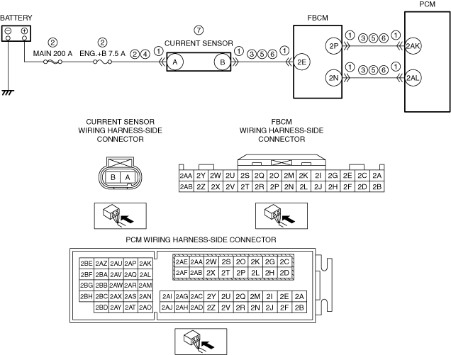
System Wiring Diagram
am6zzw00017833
|
Function Explanation (DTC Detection Outline)
Repeatability Verification Procedure
PID Item/Simulation Item Used in Diagnosis
Function Inspection Using M-MDS
|
Step |
Inspection |
Results |
Action |
|---|---|---|---|
|
1
|
PURPOSE: VERIFY IF CURRENT SENSOR MALFUNCTION IS FALSELY RECOGNIZED DUE TO OCCURRENCE OF CAN OR LIN COMMUNICATION DTC
• Switch the ignition OFF, and then switch it ON (engine off).
• Perform the DTC inspection for the PCM and front body control module (FBCM) using the M-MDS.
• Are DTCs related to CAN or LIN communication stored?
|
Yes
|
Repair the malfunctioning location according to the applicable DTC troubleshooting.
Go to the next step.
|
|
No
|
Go to the next step.
|
||
|
2
|
PURPOSE: VERIFY IF CURRENT SENSOR MALFUNCTION IS FALSELY RECOGNIZED DUE TO OCCURRENCE OF FRONT BODY CONTROL MODULE (FBCM) DTC
• Display the DTC for the front body control module (FBCM) using the M-MDS.
• Is a DTC displayed?
|
Yes
|
Repair the malfunctioning location according to the applicable DTC troubleshooting.
Go to Troubleshooting Diagnostic Procedure to perform the procedure from step 1.
|
|
No
|
Go to Troubleshooting Diagnostic Procedure to perform the procedure from step 1.
|
Troubleshooting Diagnostic Procedure
|
Step |
Inspection |
Results |
Action |
|---|---|---|---|
|
1
|
PURPOSE: VERIFY IF CONNECTOR DAMAGE OF EACH PART AFFECTS DIAGNOSTIC RESULTS
• Switch the ignition OFF.
• Disconnect the connectors of the following parts:
• Inspect the connector engagement and connection condition, and inspect the terminals for damage, deformation, corrosion, or disconnection.
• Is the connector normal?
|
Yes
|
Go to the next step.
|
|
No
|
Repair or replace the connector, then go to Step 8.
|
||
|
2
|
PURPOSE: VERIFY IF SHORT TO GROUND OR OPEN CIRCUIT IN CURRENT SENSOR POWER SUPPLY CIRCUIT AFFECTS DIAGNOSTIC RESULTS
• Verify that the current sensor connector, front body control module (FBCM) connector, and PCM connector are disconnected.
• Measure the voltage at current sensor terminal A (vehicle wiring harness side).
• Is the voltage 0 V?
|
Yes
|
Inspect the MAIN 200 A fuse and the ENG+ 7.5 A fuse.
• If the fuse is blown:
• If the fuse is damaged:
• If both fuses are normal:
Go to Step 8.
|
|
No
|
Go to the next step.
|
||
|
3
|
PURPOSE: VERIFY IF SHORT TO GROUND IN EACH WIRING HARNESS AFFECTS DIAGNOSTIC RESULTS
• Verify that the current sensor connector, front body control module (FBCM) connector, and PCM connector are disconnected.
• Inspect for continuity between the following terminals (vehicle wiring harness side) and ground.
• Is there continuity?
|
Yes
|
Refer to the wiring diagram and verify if there is a common connector between the following terminals.
• Current sensor terminal B and front body control module (FBCM) terminal 2E
• Front body control module (FBCM) terminal 2P and PCM terminal 2AK
• Front body control module (FBCM) terminal 2N and PCM terminal 2AL
If there is a common connector:
• Inspect the common connector and terminals for corrosion, damage, or disconnection and the common wiring harnesses for short to ground to determine the malfunctioning location.
• Repair or replace the malfunctioning location.
If there is no common connector:
• Repair or replace the wiring harness which is shorted to ground.
Go to Step 8.
|
|
No
|
Go to the next step.
|
||
|
4
|
PURPOSE: VERIFY IF SHORT TO POWER SUPPLY IN CURRENT SENSOR POWER SUPPLY CIRCUIT AFFECTS DIAGNOSTIC RESULTS
• Verify that the current sensor connector, front body control module (FBCM) connector, and PCM connector are disconnected.
• Switch the ignition ON (engine off).
• Measure the voltage at current sensor terminal A (vehicle wiring harness side).
• Is the voltage B+ or more?
|
Yes
|
Refer to the wiring diagram and verify if there is a common connector between the battery positive terminal and current sensor terminal A.
If there is a common connector:
• Inspect the common connector and terminals for corrosion, damage, or disconnection and the common wiring harnesses for short to power supply to determine the malfunctioning location.
• Repair or replace the malfunctioning location.
If there is no common connector:
• Repair or replace the wiring harness which is shorted to the power supply.
Go to Step 8.
|
|
No
|
Go to the next step.
|
||
|
5
|
PURPOSE: VERIFY IF SHORT TO POWER SUPPLY IN EACH WIRING HARNESS AFFECTS DIAGNOSTIC RESULTS
• Verify that the current sensor connector, front body control module (FBCM) connector, and PCM connector are disconnected.
• Measure the voltage at the following terminals (vehicle wiring harness side).
• Is the voltage 0 V?
|
Yes
|
Go to the next step.
|
|
No
|
Refer to the wiring diagram and verify if there is a common connector between the following terminals.
• Current sensor terminal B and front body control module (FBCM) terminal 2E
• Front body control module (FBCM) terminal 2P and PCM terminal 2AK
• Front body control module (FBCM) terminal 2N and PCM terminal 2AL
If there is a common connector:
• Inspect the common connector and terminals for corrosion, damage, or disconnection and the common wiring harnesses for short to power supply to determine the malfunctioning location.
• Repair or replace the malfunctioning location.
If there is no common connector:
• Repair or replace the wiring harness which is shorted to the power supply.
Go to Step 8.
|
||
|
6
|
PURPOSE: VERIFY IF OPEN CIRCUIT IN EACH WIRING HARNESS AFFECTS DIAGNOSTIC RESULTS
• Verify that the current sensor connector, front body control module (FBCM) connector, and PCM connector are disconnected.
• Switch the ignition OFF.
• Inspect between the following terminals (vehicle wiring harness side) for continuity.
• Is there continuity?
|
Yes
|
Go to the next step.
|
|
No
|
Refer to the wiring diagram and verify if there is a common connector between the following terminals.
• Current sensor terminal B and front body control module (FBCM) terminal 2E
• Front body control module (FBCM) terminal 2P and PCM terminal 2AK
• Front body control module (FBCM) terminal 2N and PCM terminal 2AL
If there is a common connector:
• Inspect the common connector and terminals for corrosion, damage, or disconnection and the common wiring harnesses for an open circuit to determine the malfunctioning location.
• Repair or replace the malfunctioning location.
If there is no common connector:
• Repair or replace the wiring harness which has an open circuit.
Go to Step 8.
|
||
|
7
|
PURPOSE: DETERMINE INTEGRITY OF CURRENT SENSOR
• Inspect the current sensor.
• Is the current sensor normal?
|
Yes
|
Go to the next step.
|
|
No
|
Replace the current sensor, then go to the next step.
|
||
|
8
|
PURPOSE: VERIFICATION OF VEHICLE REPAIR COMPLETION
• Reconnect all disconnected connectors and hoses.
• Refer to the [MEMORY CLEARING PROCEDURE] and clear the DTC.
• Implement the repeatability verification procedure.
• Display the DTCs using the M-MDS.
• Is DTC P058A:00 displayed?
|
Yes
|
Repeat the inspection from Step 1.
• If the malfunction recurs, replace the PCM, then go to the next step.
|
|
No
|
Go to the next step.
|
||
|
9
|
PURPOSE: VERIFY IF THERE IS ANY OTHER MALFUNCTION
• Has any other DTC or pending code been stored?
|
Yes
|
Repair the malfunctioning location according to the applicable DTC troubleshooting.
|
|
No
|
DTC troubleshooting completed.
|